Complete Guide to the basics Autodesk Revit (MEP focused)
Index (Click to go to the Topic)
Set / Customise your Working Tools
Understanding the View Controls in Revit 3D: Basic operations
Linking a CAD file as Reference
Picking / Tracing Gridlines from AutoCAD to Revit
View Range
Keyboard Shortcuts (KS)
Revit Modify Tools
Move an Object (MV)
Copy and Paste an Object (CO)
Align (AL)
Offset (OF)
Rotate (RO)
Trim or Extend to Corner (TR) / Trim or Extend Single Element
Trim or Extend Multiple Elements (TT)
Mirror Pick Axis (MM)
Mirror Draw Axis (DM)
Split (SL) / Split with Gap
Array (AR)
Scale (RE)
Import CAD
Model-in-place a Component
Visibility Graphics (VG)
How to use Filter in Revit
Project Unit
Drawing ACMV Ducts in Revit
Step 1: Set the View’s Detail Level
Step 2: Set Routing Preference
Step 3: Start Drawing a Duct
Step 4: Continue drawing the Duct with the fittings auto-generated from the routing preferences
Step 5: Air Terminals
Step 6: Draw a duct Vertically
Step 7: Draw a Flexible Duct
How to Generate a Duct Pressure Drop Report with Revit
How to Export to Navisworks (DWF)
Add Landscape, Site Ground and Topography
Adding Furniture
Adding Walls
Adding Doors and Windows
Adding Floor Slab / Ceiling / Roof
Adding floor tiles
Annotation (Dimension)
Annotate (Tag by Category)
Adding Annotation in 3D view / Locking or Creating a new 3D view
Annotation in 3D
Assigning / Changing the Colour of a System
Isolate
Changing the System Type of Duct or Pipe Networks
To add text
Adding Sections
Elevation
Drawing Staircase
Copy and Paste Aligned to Selected Levels
Room Label and Colour Fill
Printing Sheet / Titleblock


Open Application
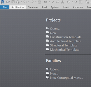
To open an existing project, click “Open…”.
To create a new project file, click “New…”. Creating a new project will prompt you to select a template to work from. For Mechanical related drawings, choose “Mechanical Template” and then click “OK”.

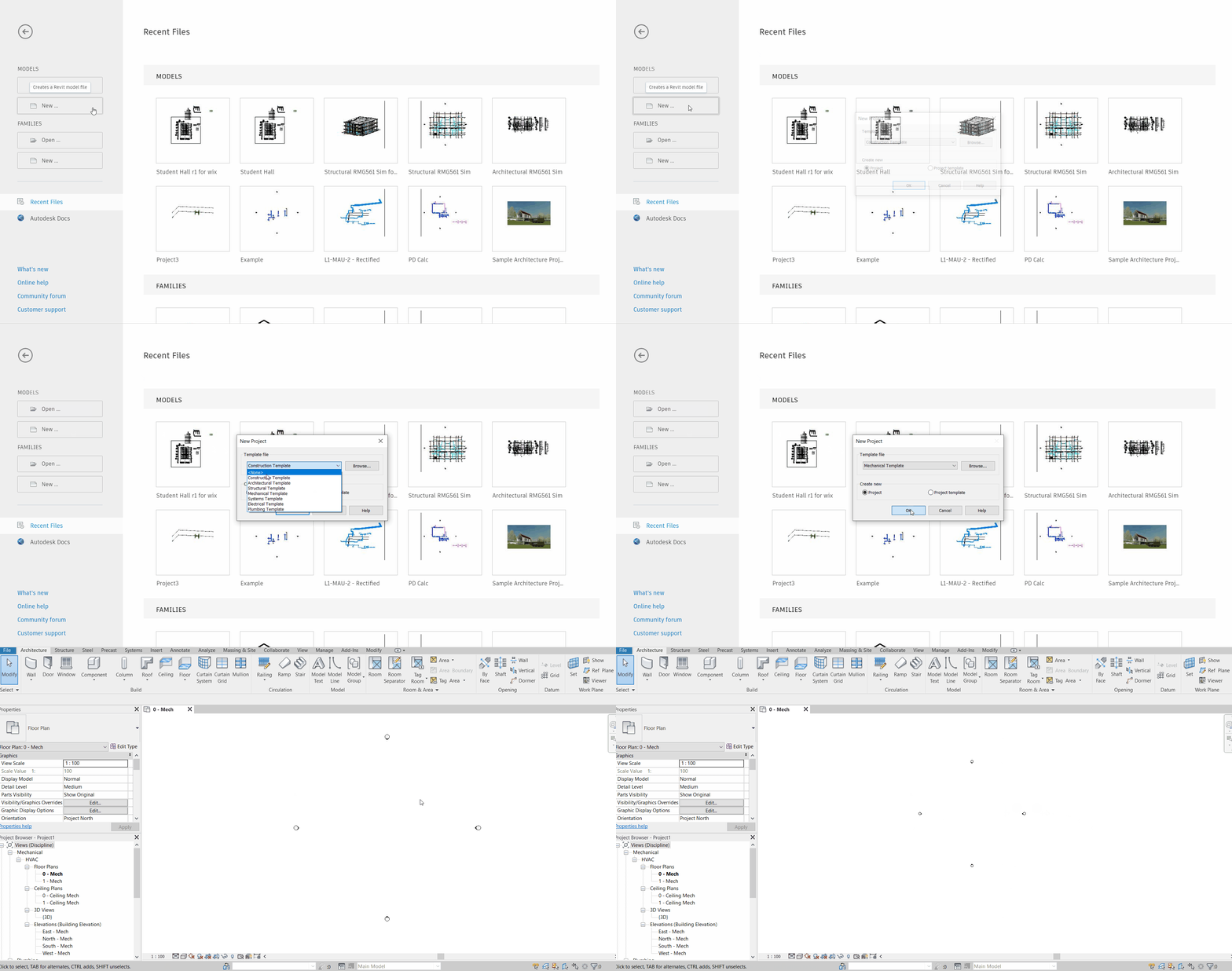
Once you created a new project. Your new project will be named as “Project 1” by default. Browse to a folder or path you want to keep your project file in. You will then come across an empty sheet of workspace where you can start sketching on.

Setting the Background Colour
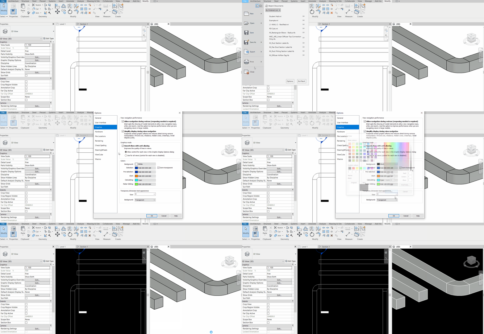
In contrast to AutoCAD, the default background colour for Revit is white. To change your background colour, go to File > Option > Graphics > Colours > Background. Change the existing colour to your desired colour. Then Click “OK”.

Set / Customise your Working Tools
Next, you will need to customise your own user interface and get yourself familiarize with it.
Go to the “View” tab > User Interface > Check the 3 browsers: Project Browser, System Browser and Properties.

Checked browsers should appear as separate windows straightaway. Drag them to where you feel comfortable to have them at. For personal preference, I like to combine them into one window with separate tabs as shown highlighted below, to the left of my workspace. Sometimes these windows do not appear even when it is checked in the user interface. If you are using a second monitor to extend your screen, the browser might be “hidden” in the second screen (even when the monitor is being disconnected).

Understanding the View Controls in Revit 3D: Basic operations
It is easy to master the basic operations of Autodesk Revit. Despite some differences from AutoCAD, most of the operations/control are the same.
To pan – Hold down the scroller of your mouse and move the cursor in desired directions
To zoom – Use the scroller to zoom in and out
To select – The selection of objects in Revit is slightly different from that in AutoCAD. One single click registers the selection for an object. To select multiple objects, you will need to hold down the left-click of your mouse, drag across the desired objects, and release only when whole of them are included. Selected objects also become highlighted in blue.
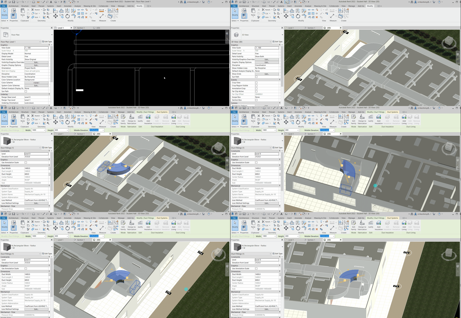
To rotate view – If you are in 3D view, and need to look around an object for coordination, pan (hold down scroller) with your shift key held down enables view rotation. Always select an object of interest (or any nearby, small object) first so that Revit will treat it as the point of interest or the centre for rotation. Otherwise, you might end up revolving around the entire floor plans (or previously selected objects), hence eventually lose track of where you want to focus.
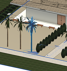
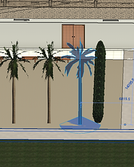

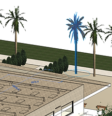
Figures above show that the view can be rotated around the selected tree as the centre point of interest. GIF below shows a rotation around a duct elbow as the center of rotation.
The Views in Revit
By default, Revit included a list of views in the project browser that included “Floor Plan”, “Ceiling Plan”, “Elevation” and “3D views” for each project template. They are fully customisable – simply right-click on a view in the project browser, and you will be able to delete, rename or duplicate & rename a view. To open a new tab, double-clicking on any of the views. These also apply to all other views in the project browser, such as “Sheets” (for printing), “Schedule/Quantities”, or family files.

You may delete any unused views or those with non-relevant sub-disciplines.
Understanding how the project browser systematically orders different views in its hierarchy is quite simple. Each of the windows (or tabs) of view has its own “View Properties”. The properties pane defaults the properties setting to that of the view when no object is selected.
For example, as shown below, we are now in the view tab “East – Mech”, the properties pane is available for the setting of this particular view, for parameters such as discipline, sub-discipline, and visibility/graphics. By setting the discipline and sub-discipline for each of the views in the properties pane, and then deleting unused views, we will be able to customize a clean and systematic project browser for our project. Note that sub-disciplines only appear in Mechanical, Electrical and Plumbing (MEP) templates.

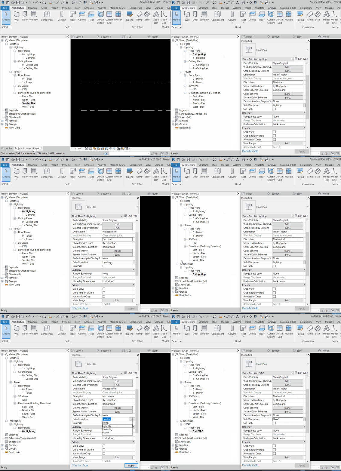
If no information were provided in the properties pane, Revit might resemble it with 3 question marks “???” in the project browser as shown above. Whenever a parameter is entered or selected, always click “Apply” at the bottom right corner for the actions to take effect.
It is important to understand that the “View” system in Revit is well-designed in a way that all different “Views” are referencing the same project file in real time. In other words, if you add an object in a plan, it will be reflected almost instantly in the 3D view, provided the level, visibility and filter settings for the view allow for the added object to be shown. These view settings are unique for each view. For instance, we can add an object in the plan view but hide it in the 3D view within the same project file.
As a simple example, we add a duct network and a pipe network in a coordination view. Then, we can create two 3D views, one showing only the duct network and the other showing only the pipe network. They can then be placed into different sheets for printing. Note that they are both referenced from the same coordination view. Only the unique settings from each view “hide” certain information away. From the same piece of coordination drawing, you can extract as many combinations of information you like into each view, for as many views you would like to create.

To ease things out, Revit has defined the sub-discipline that may be helpful for further discrimination between MEP services. If the discipline of a view is set to “Plumbing”, most probably you can only see plumbing services in the view (Otherwise, you may set in “Visibility Graphics” that only plumbing services can be seen in the view). If you would like to have a view that includes all disciplines, set the view’s discipline to “Coordination”.
One popular practice is to utilize the 3D view as my coordination view. Use a second screen (an extended monitor) to display only the 3D view. As we draw in plan views, we take note of the real time changes reflected in the 3D view window. We can take note if any of these newly drawn objects clash with the existing, and to know what really happened if the drawn item does not show up in the plan views. If you only have one monitor, consider using the tile windows (View > Tile Windows)

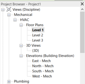
A common structure of the hierarchy in our project browser can be Discipline > Sub-discipline > Type of View > View (for example, Mechanical > HVAC > Floor Plans > Level 3) as shown below. To create new view, go to > View > Plan Views, and then select the type of plans you want to create.

You probably would not be able to see anything in the list when you have the box “Do not duplicate existing views” checked. Checking this box will have Revit helps let us know that floor plans for all levels have already existed in the project browse. If we insist to add, there will be a duplicate of the level’s view in the same sub-discipline (We may also add the view by right clicking the view and then click “Duplicate View”). Right-click on the views to delete any unwanted duplicate views or amend the view settings to resemble that of a new desired view.

A typical organised project browser is shown in the example below.
Use a Section Box in Revit
A section box is very useful in 3D view in Revit. It helps to set the boundary of the 3D view so that you can see beneath obstructions such us a Roof, or the level above. To use the section box, simply check the box for Section Box in the View’s Properties Pane.
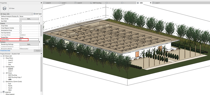
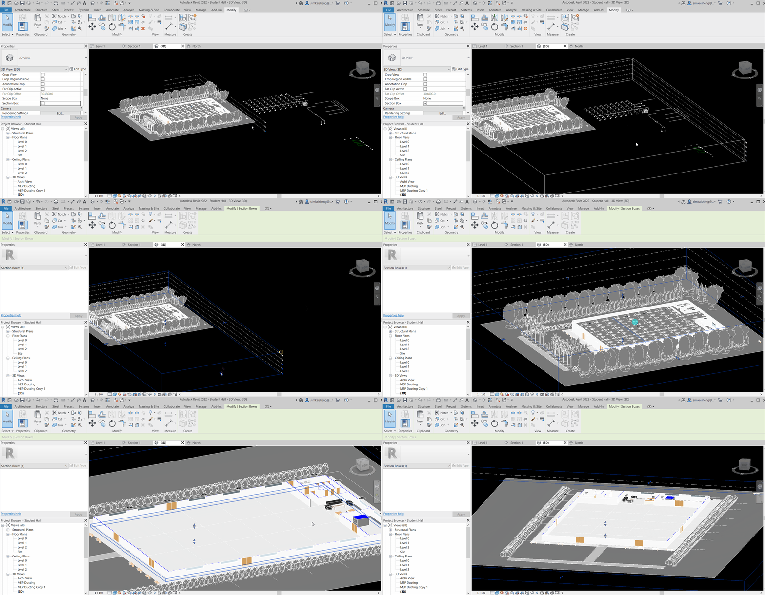
A rectangular section box can then be seen as shown below. Click on the box and look for the arrow as shown below. Click either side of the arrow to extend or shrink the height, length and width of the section box. Hold down the arrow and drag for box size adjustments.

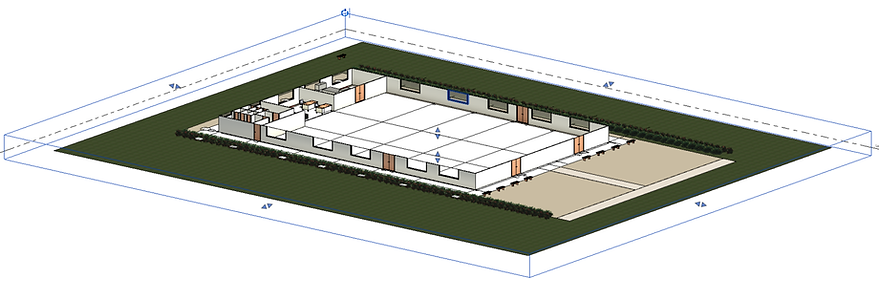
Figure: Lowered height of the section box allows a cut-through 3D view underneath the roof and ceiling. Uncheck the Section Box in Properties Pane to return to the original view.
Setting the Levels
To begin with, you will need to let Revit know the elevation (height) for the levels you are working on. You can set your elevation details in the elevation view. Go to your Project browser > Expand the dropdowns to elevation and double-click to open an elevation view.

Adding a new Level
There are several ways to add levels. First, in one of the elevation views, click Architecture > Datum “Level”.
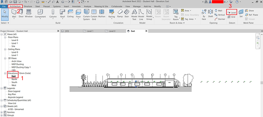
Then, start to guide your Level Datum across from the left to the right of your elevation view. You may adjust the height for the level in the figures highlighted below.
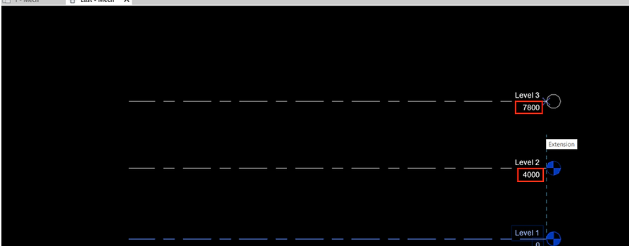
Click “ESC” after you have done adding a new level. By default, a new level will appear in your views in the project browser, and a plan view is created as long as “Make Plan View” option is kept checked. Rename all added views to your preferred convention.

To add several levels, explore using “Copy” and “Paste” with reference, or “Pick Lines” function (explained later). It is notable that if you copy & paste a level datum, the view will not be created automatically. In this case, we will need to create the corresponding plan view for the added levels. Just go to > View > Plan Views, and then select what plans you want to create for what levels.
Drawing Grid Lines
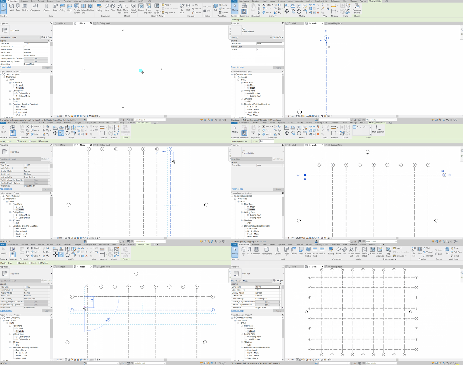
Similar to drawing level datum on elevation, drawing Grid Lines on plans is simple:
Go to > Architecture > Datum > Grid

Draw your gridlines for both vertical and horizontal grid. If you change the Gridline label from “1” to “A” (just double-click on the text in the bubble), the corresponding parallel gridlines will have the sequence automatically updated in an incremental manner from the first one. For example, “B”, “C”, “D”, etc.

If you have a layout plan in CAD to trace from, you can “reconstruct” the Grid line into your Revit Model by using the “pick-lines” function (refer “Tracing Gridlines from AutoCAD to Revit”).
To change the direction of the grid line label, click on the grid line and look for the small check. Uncheck the side you do not want to have the label on, and check the side you want to have the label. To save time, do this before you populate the other grid lines.
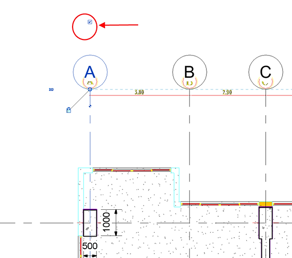

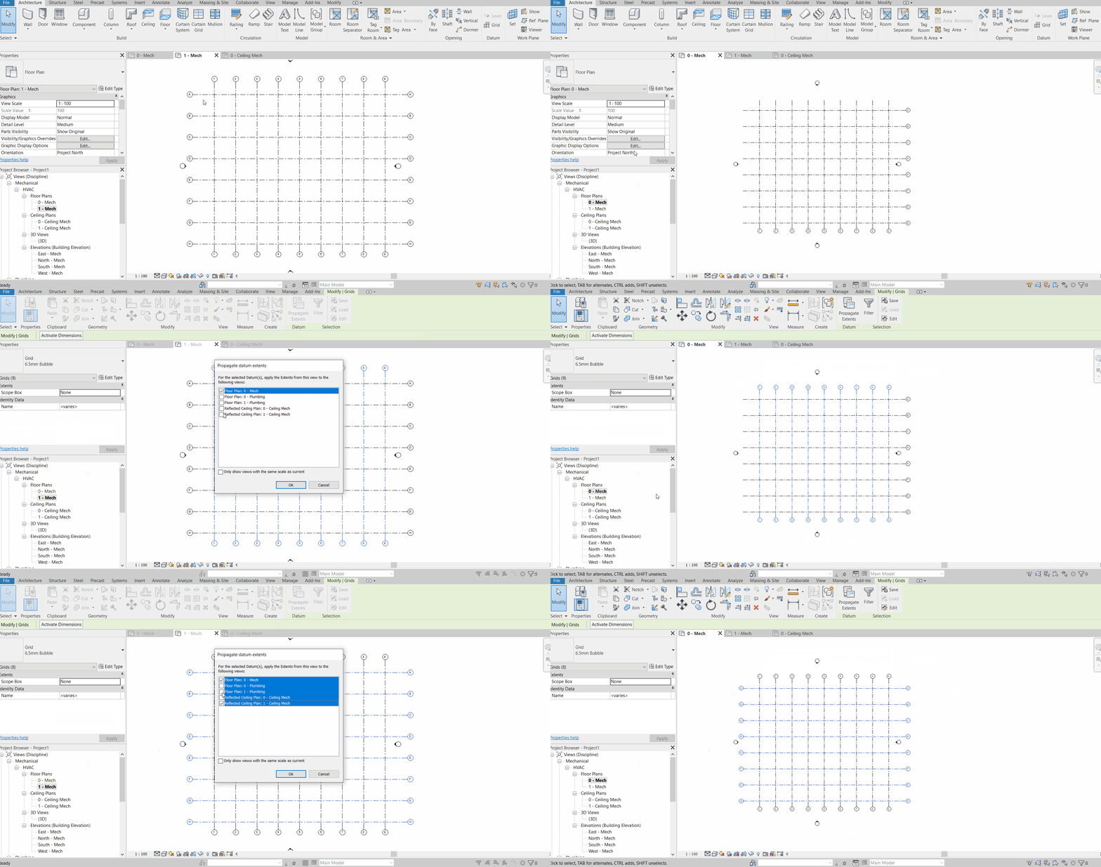
To repeat this setting for the other floors, select the relevant Grid Lines and use “Propagate extents”.
Hold down the “Shift Key” to select the floors you want the Grid Lines properties to be extended to, then click “OK”.

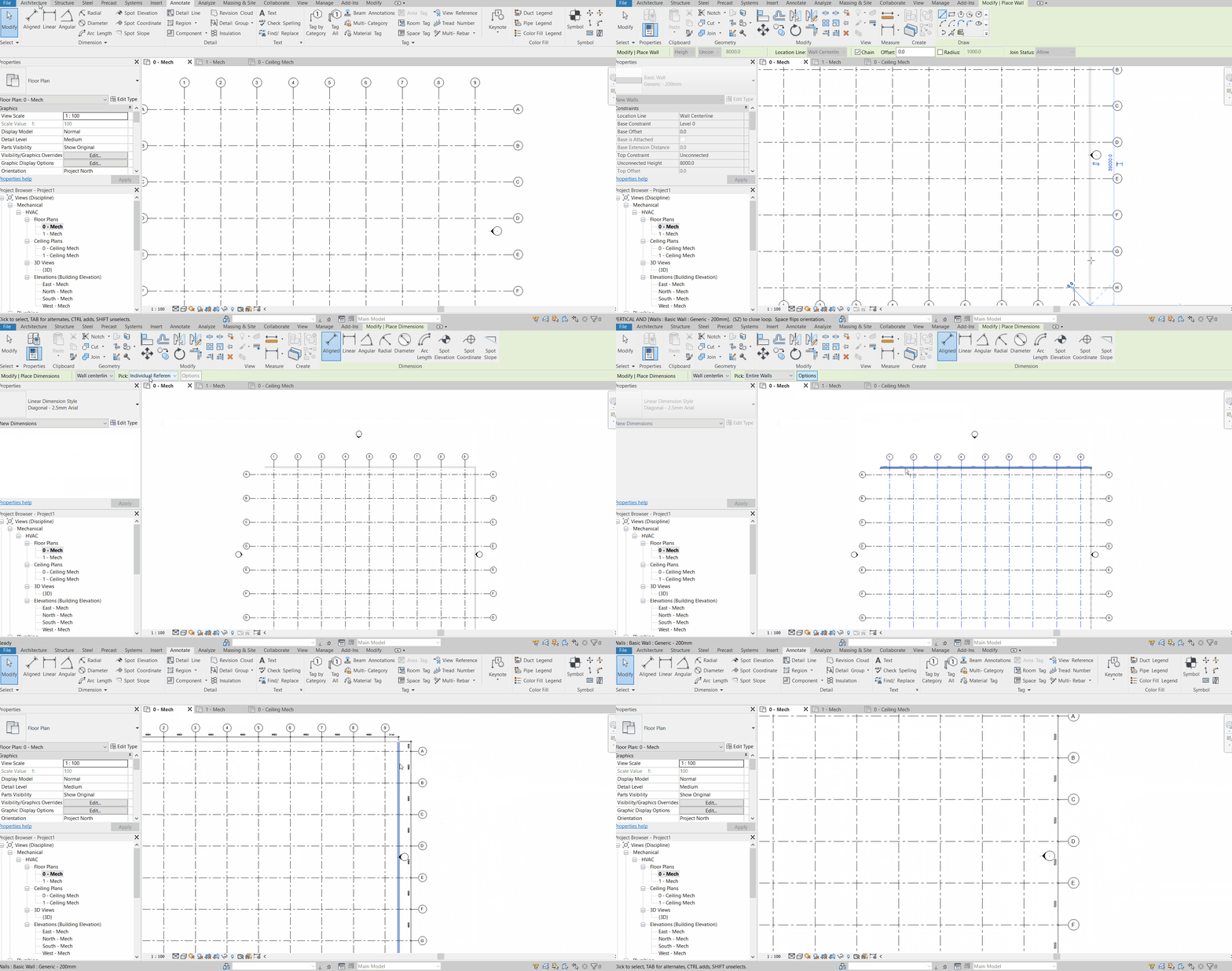
You may annotate the grid lines by adding walls across the grid lines, and then annotate the entire walls intersecting with the grid lines.
Linking a CAD file as Reference
As of the time of this publication, there is no way we can convert a 2D CAD file into a 3D Revit project file. However, linking a CAD file as a reference (we call “Link”) is very useful, especially when we have all the Architectural plans in CAD and would like to input our M&E services directly in Revit.
Go to the “Manage” tab > Manage Links (in the Manage Project ribbon) > CAD Formats > Add… > Select the CAD file to link > Open > Apply > OK


After a file is linked it will appear as an item in the list in the same table as shown below. To unload the link, go to this table (Manage > Manage Links > CAD format), select the relevant item(s) and click “Unload”. Click “Apply” and “OK” for the unloading to take effect. The link can be repeatedly unloaded and reloaded whenever necessary, provided the destination path to the linked file remains the same. If it has been changed, select the item, and then click “Reload from…” to re-browse to the new destination path.

If you cannot see your linked CAD, it might not be visible in your current view. As mentioned, an object that exists in the project file may not be visible in a view unless the view setting fulfils every criterion – be it the height or levels, discipline, Graphic Settings, Filter settings, or View Depth. Each of the views are unique and can be set with different settings for all these criteria.
Once you click “OK”, your CAD file layout will appear in your workspace. There are several settings to be done to this linked layout. Firstly, we want to make sure this layout is at the correct elevation. Because it is a Level 1 Floor Plan, we want to make sure its base level is set at “Level 1”, with 0 height offset. This can be set at the properties pane when an object is selected.

However, before we can even move it, we need to make clear of 2 things. Firstly, the linked layout should be able to be selected. Go to the small icons on your bottom right corner, first from the left – “Select Links”, and toggle it so that the linked element can be selected.
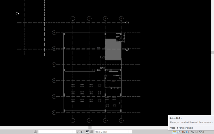
Secondly, we want to make sure the linked element is not pinned. Pinned element cannot be moved, and neither can it even be selected if the “Select pinned elements” setting is turned off. Make sure the tiny icon at the bottom right corner has no red cross so that you are able to select the layout (if pinned).

With that, we can then pin/unpin a selected object by clicking on the mini “pin” icon when that object is selected.

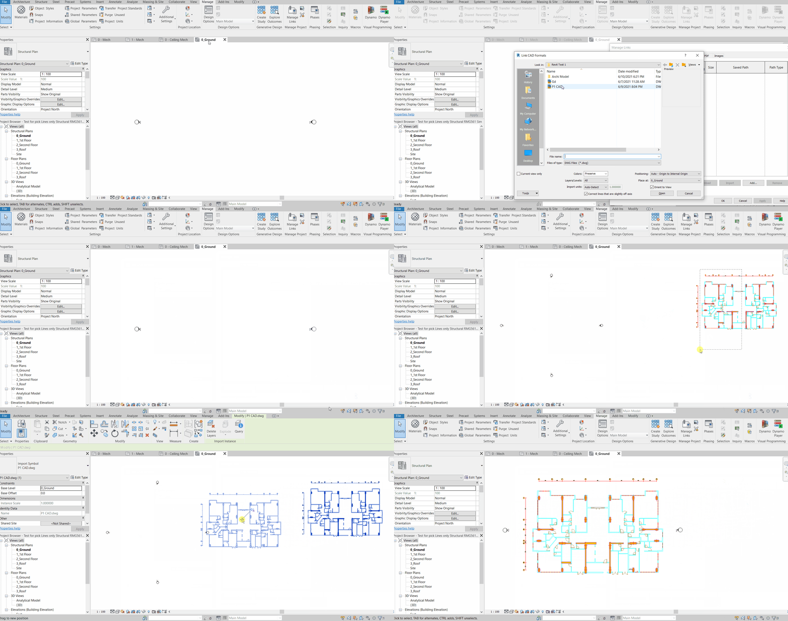
If we already have gridlines in our Revit, we would like to move the linked layout to align with our drawn Grid Line in Revit for both axes. Use the “ALIGN” command by typing “AL” on your keyboard (without the need to hit “Enter” thereafter), followed by a click on your Grid Line A in your Revit Model, and subsequently a click on your Grid Line A in your linked CAD layout. Then, repeat the step for your Grid Line 1. Now, you are able to lay your CAD model accurately onto your Grid Lines on the x-y plane for both axes.
Picking / Tracing Gridlines from AutoCAD to Revit
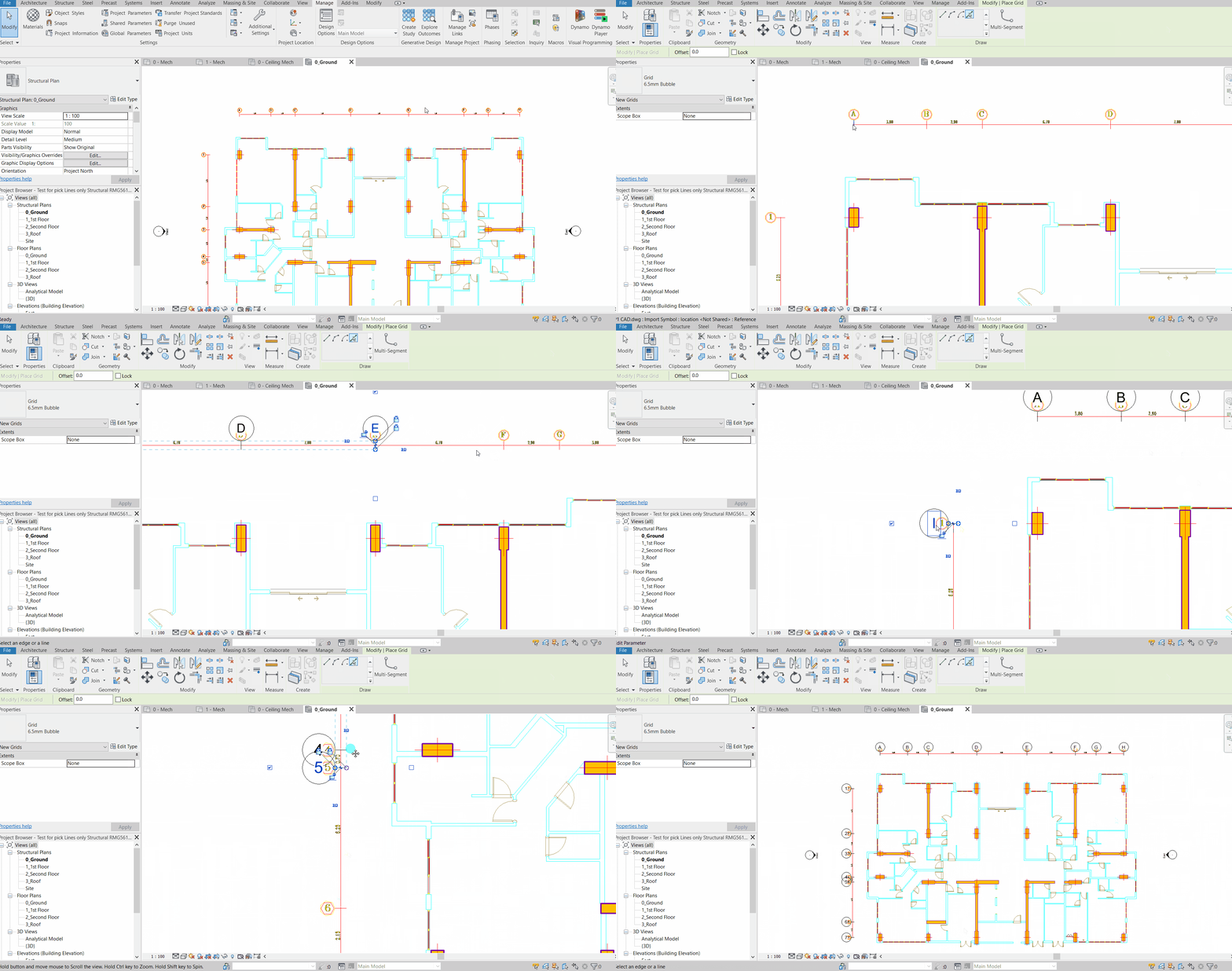
If you have not constructed your Grid Line in your Revit Model, and prefer to use the linked layout to “reconstruct” the Grid Line into Revit, simply go Architecture > Grid Lines (Datum) > Modify / Place Grid > Pick Lines. Simply click on the green “Pick-Lines” icon, and then start picking the lines in the linked CAD layout.
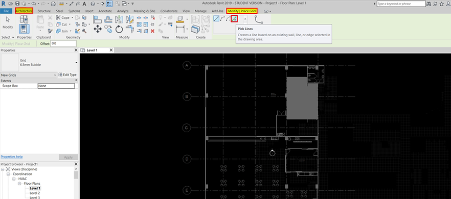
Edit your first Gridline label to suit your numbering style, and the rest of the lines should follow suit. For example, you might want to change the label for your first picked line from A to 1 for your Grid line parallel to the y-axis, and label 1 to A for those parallel to your x-axis. Do it for the first line you picked. Revit will take care of the rest of the lines picked accordingly.
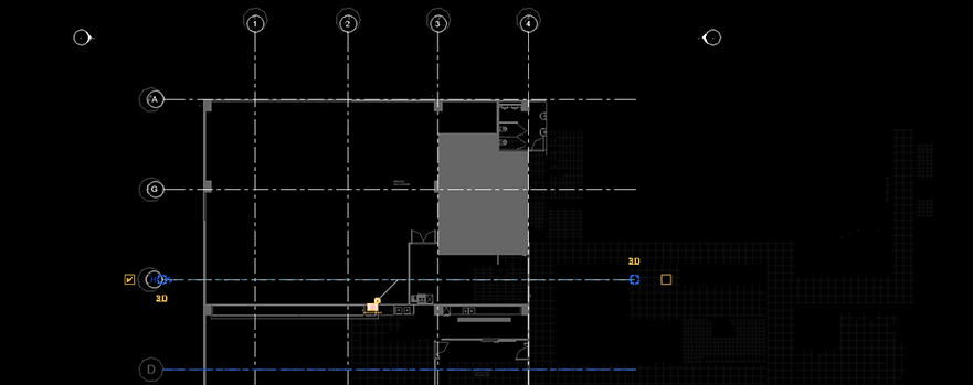
The grid lines shall appear by default for the rest of the levels. We can perform the linking of the CAD file for the rest of the levels and repeat the steps for each of the levels. When we are working on a level, just “turn off” the rest of the CAD layouts of other levels at the “Manage > Manage Links” windows by unloading the levels. We just need to “Re-load” the link file when we start working on that level again. Otherwise, you can keep all levels loaded (might affect your graphic performance) and setting the “View Range” of a level’s view to restrict the appearance of unrelated levels. For simple understanding, if you are able to see Level 1 CAD file link when you are working on Level 2, we need to set the View Range (depth of view) for level 2 to be higher. Nevertheless, the easier way is still to unload Level 1.
After you are done with all the Gridlines, levels & link settings, and would like to start inputting your MEP services into it, you can now pin the linked layout to restrict movement (so that you won’t accidentally shift the linked layout) and turn off “Select pinned element”, or “Select Links” (so that we will not be annoyed by the background got selected when we intend to select our MEP services). After all, the Architectural layout will just act as a reference for us to input our MEP services.
View Range
One of the steps we may need to do is to set the View Range (VR) (Apart from the Visibility Graphics (VG)) in your specific views. Use the keyboard shortcut “VR” for View Range.
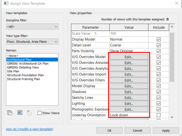
In some cases, you will find some of your view settings or properties cannot be edited. It appears to be greyed out and keyboard shortcut commands just don’t work. The reason is because the properties are being controlled and associated with a pre-set View Template. To edit properties for each view, dissociate the view from the template so that each view retains its individual properties, but future changes to the template no longer affects the dissociated view.
To dissociate a view from a view template, click the button next to the View Template (In this case “Mechanical Plan”) in the Properties palette, and then select “None”.

Alternatively, keep the view associated to the template, and edit the properties through the associated template instead.
The details and illustration provided by the official Autodesk page best describes the parameter settings for View Range, and the video explanation by Balkan Architect provide good explanation.
Keyboard Shortcuts (KS)
Use the keyboard shortcut “KS” to initiate our keyboard shortcut settings. Here, we can search for any commands such as drawing a duct (DT), pipe (PI), move (MV), copy (CO), trim/extend (TR), to check for assigned keyboard shortcut keys. We can assign new keys for all commands, some of which are assigned by default by Revit. We can even utilise modifier keys such as Shift and Control in the new key assignment.
Revit compiles some of the default Revit shortcut keys for useful commands into a PDF file.

Revit Modify Tools
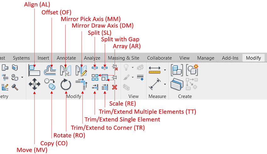
Basic modify tools in Revit is in the modify ribbon as shown below. If you hover your cursor over any of them for some time, Revit will show the preview of how to work out each tool.
Move an Object (MV)
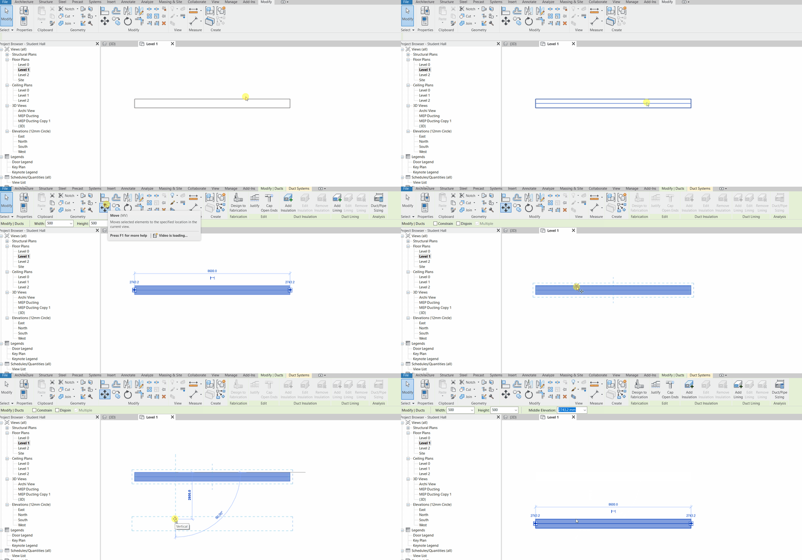
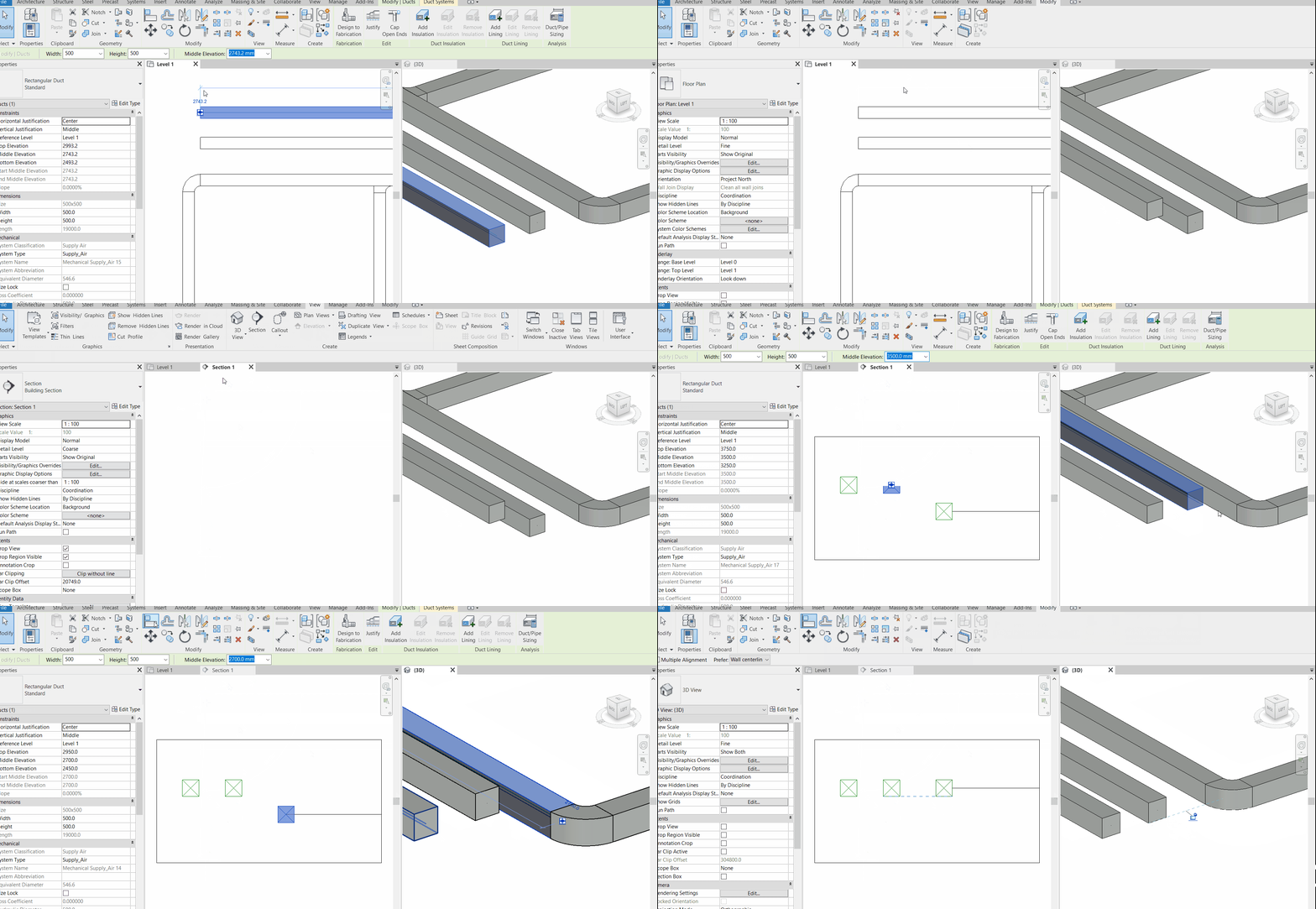
Moving an object vertically (in the z-axis) can be done by adjusting the elevation of the object on the ribbon or properties pane (offset with respect to the base reference level), or using the command Move (MV) or the arrow key in section or elevation views.
Copy and Paste an Object (CO)
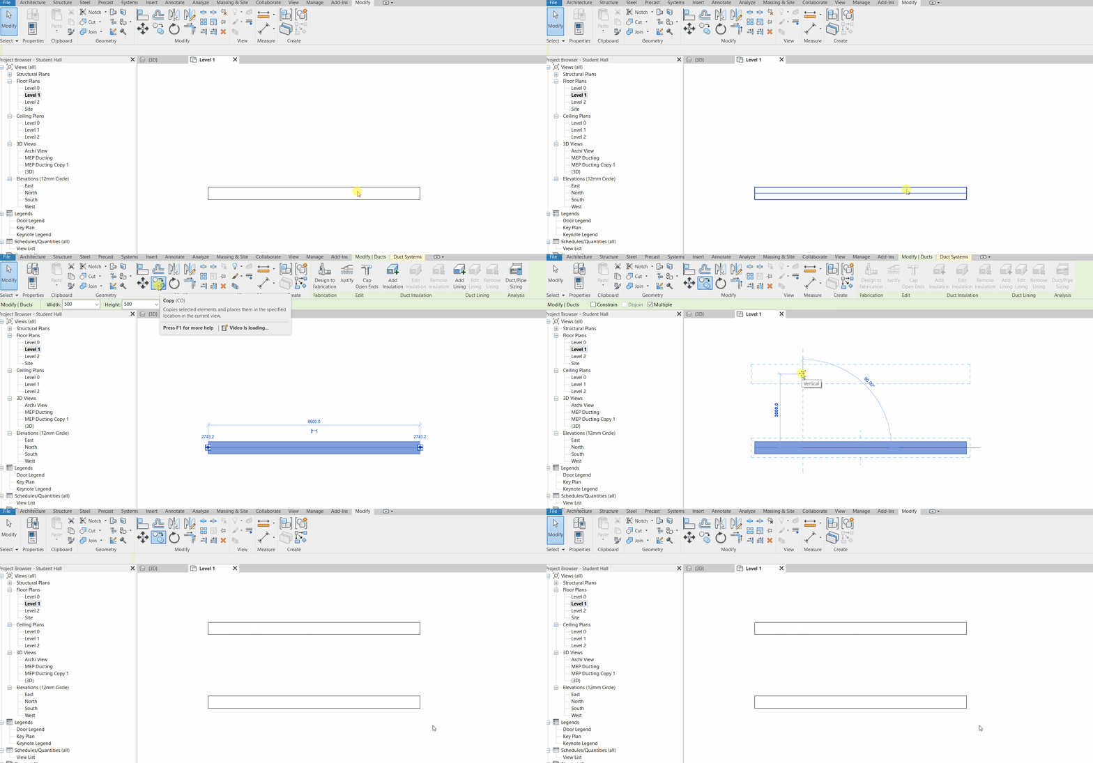
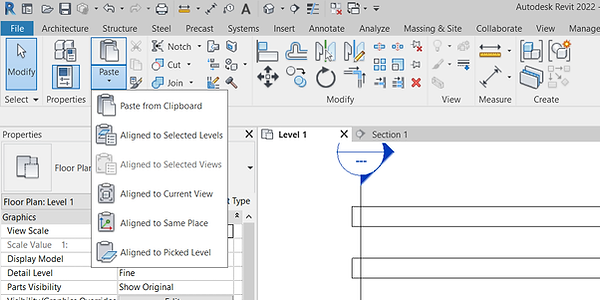
There are several options for pasting a copied object when we click the drop-down list below the paste button.
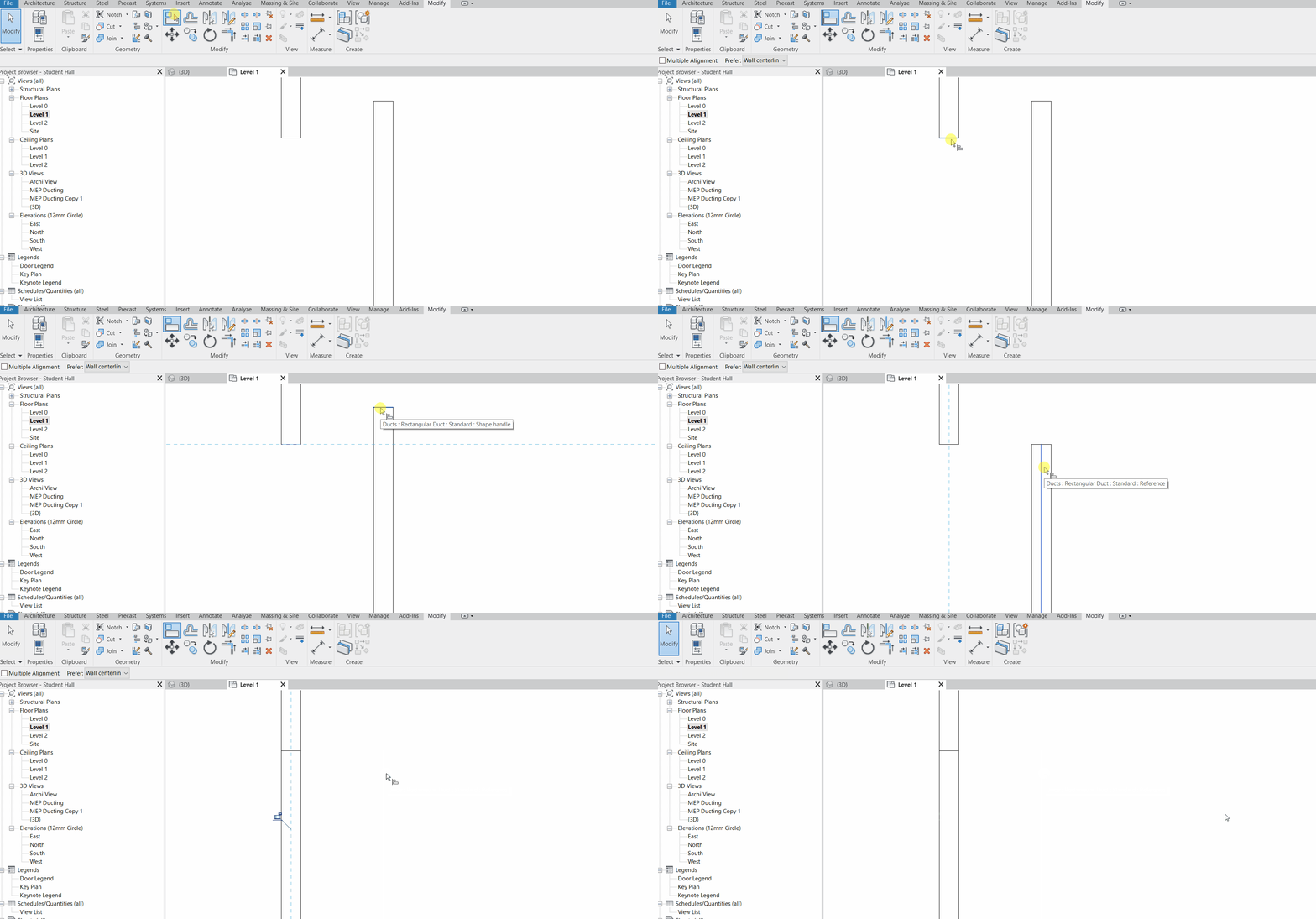
Align (AL)
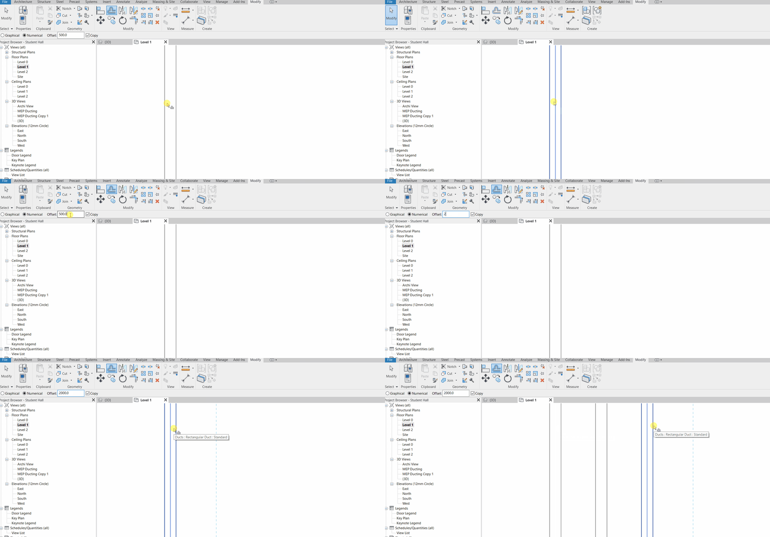
Offset (OF)
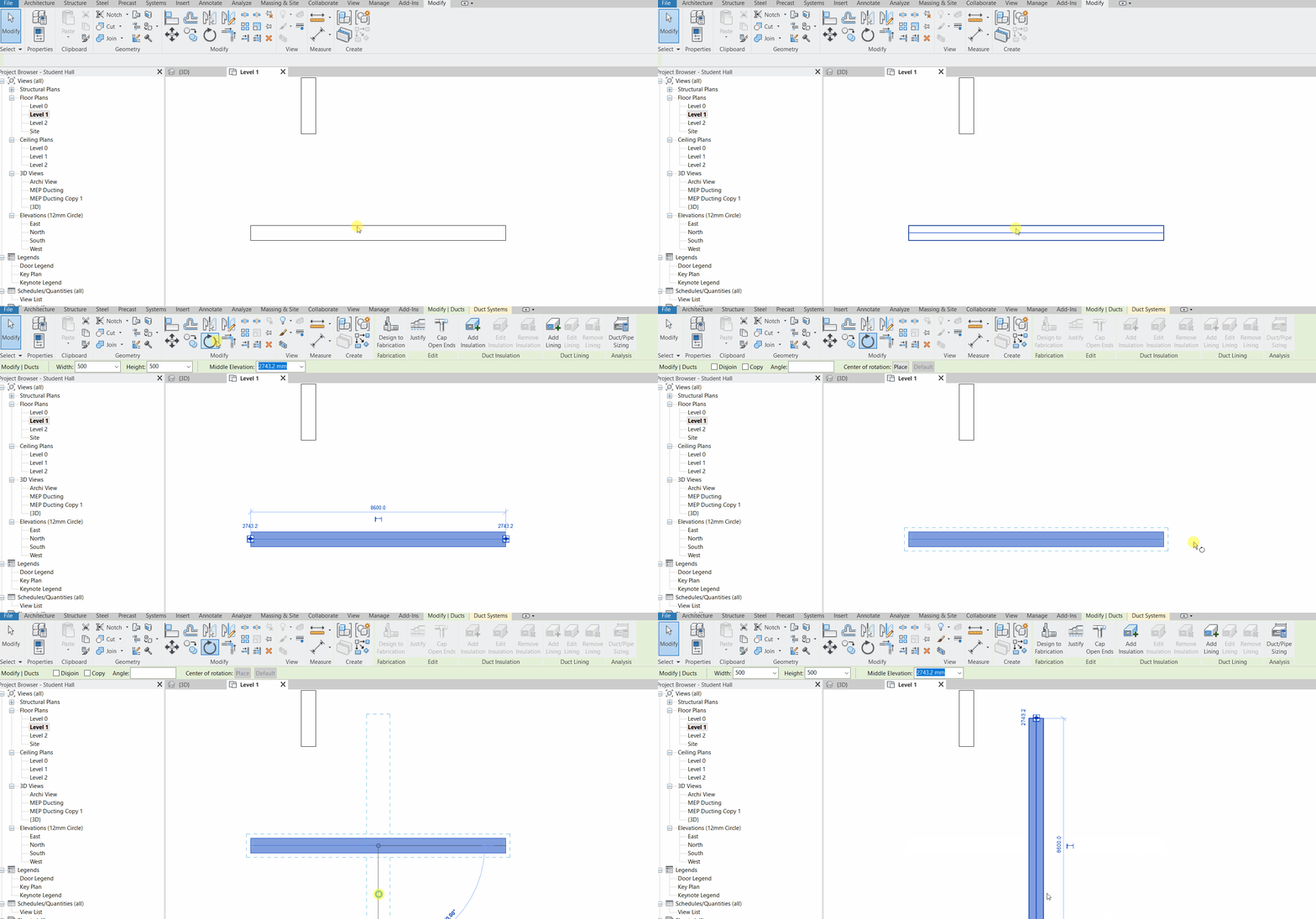
Rotate (RO)
Trim or Extend to Corner (TR) / Trim or Extend Single Element
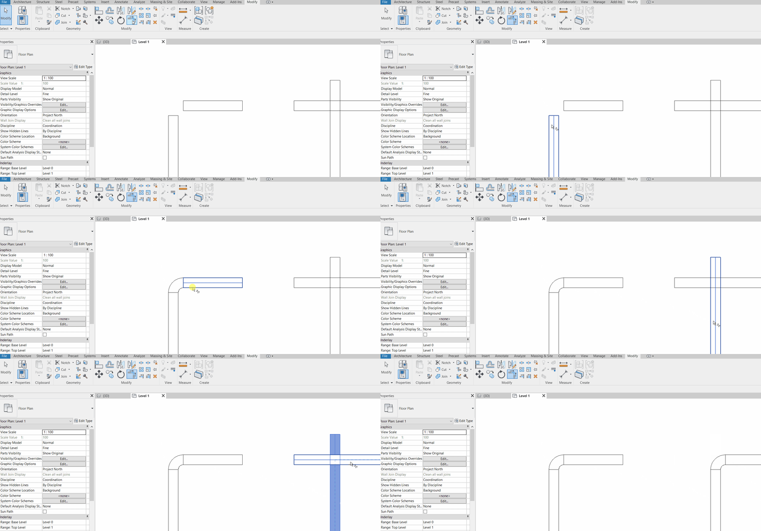
Trim or Extend Multiple Elements (TT)
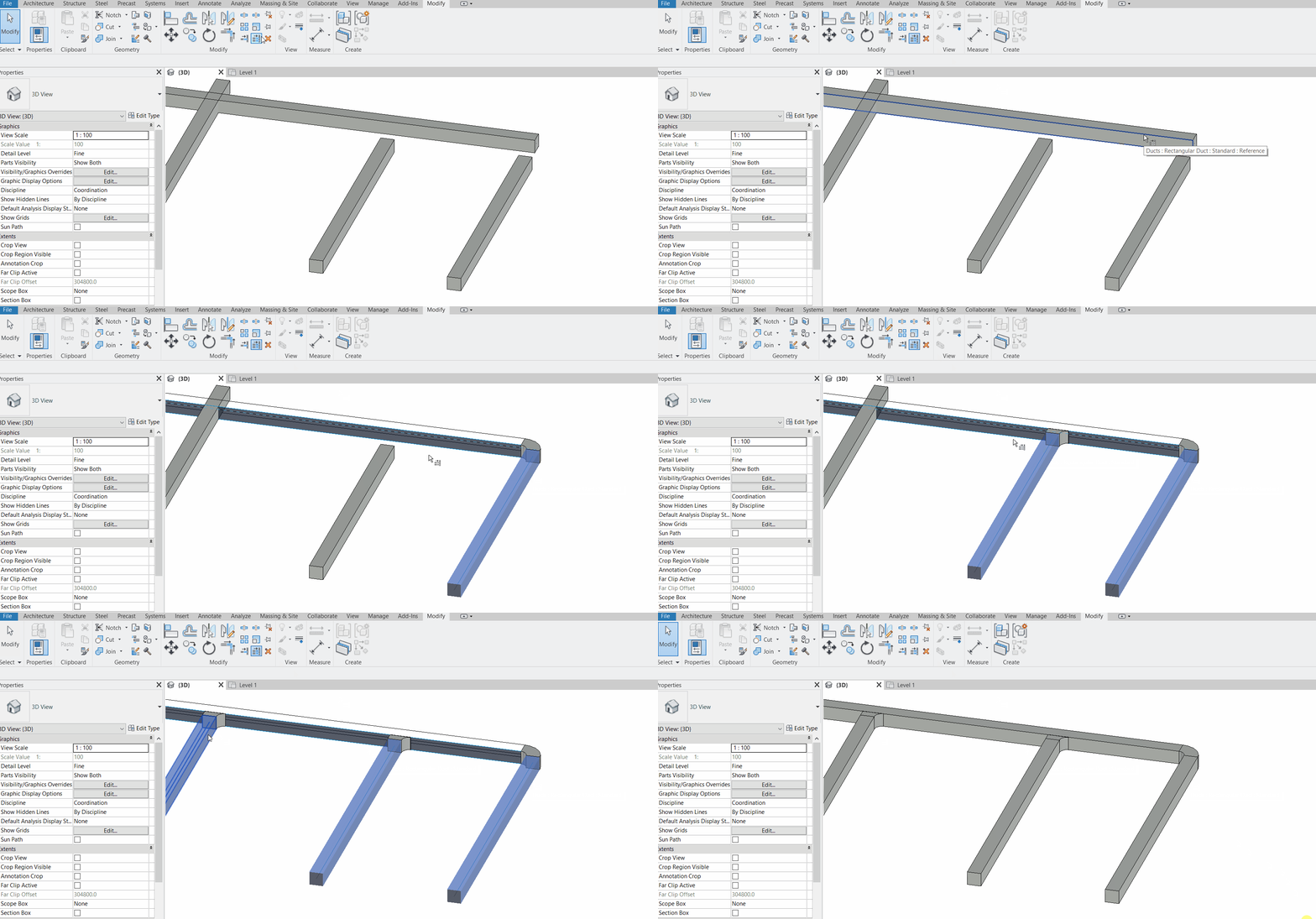
Mirror Pick Axis (MM)
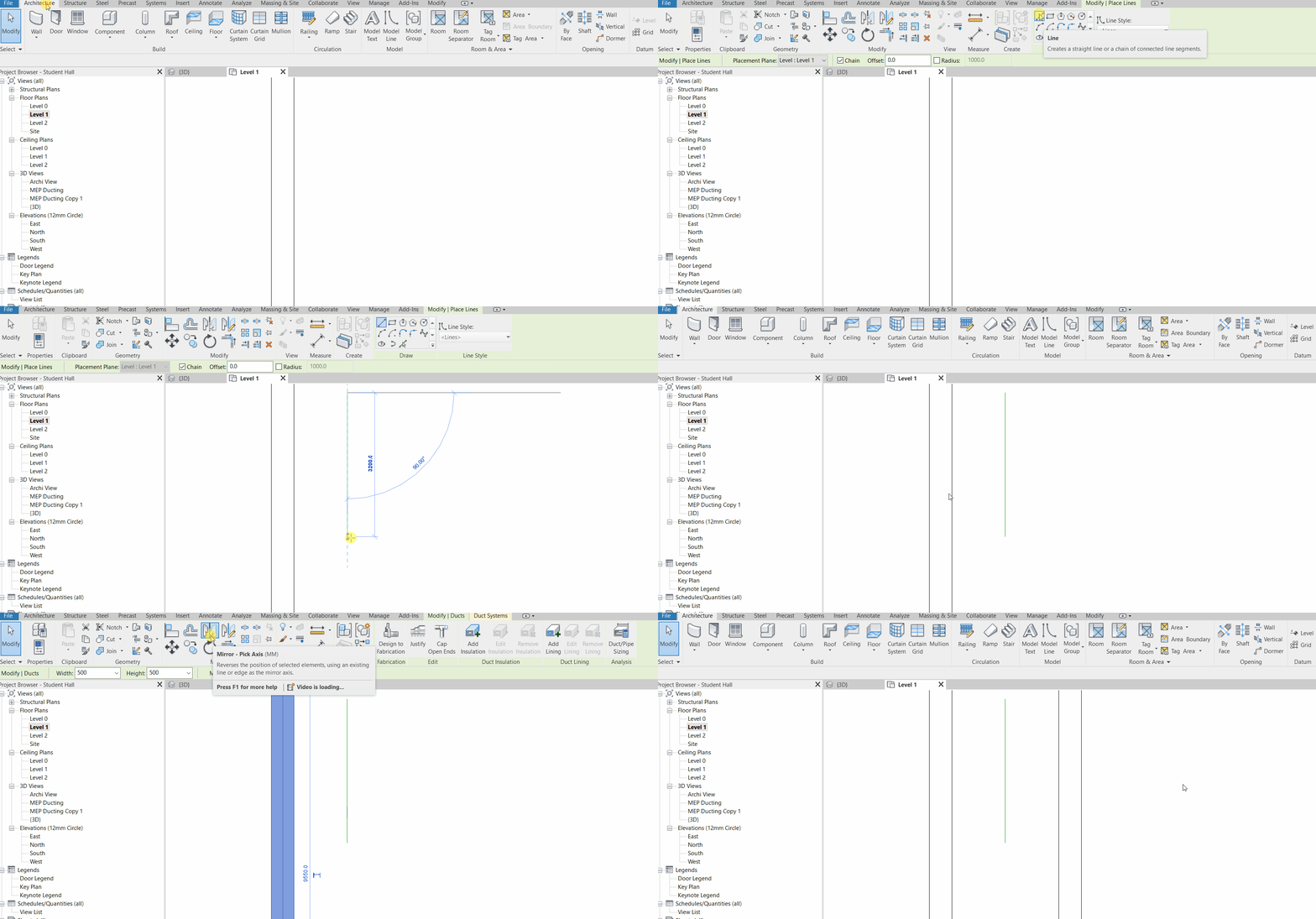
Mirror Draw Axis (DM)
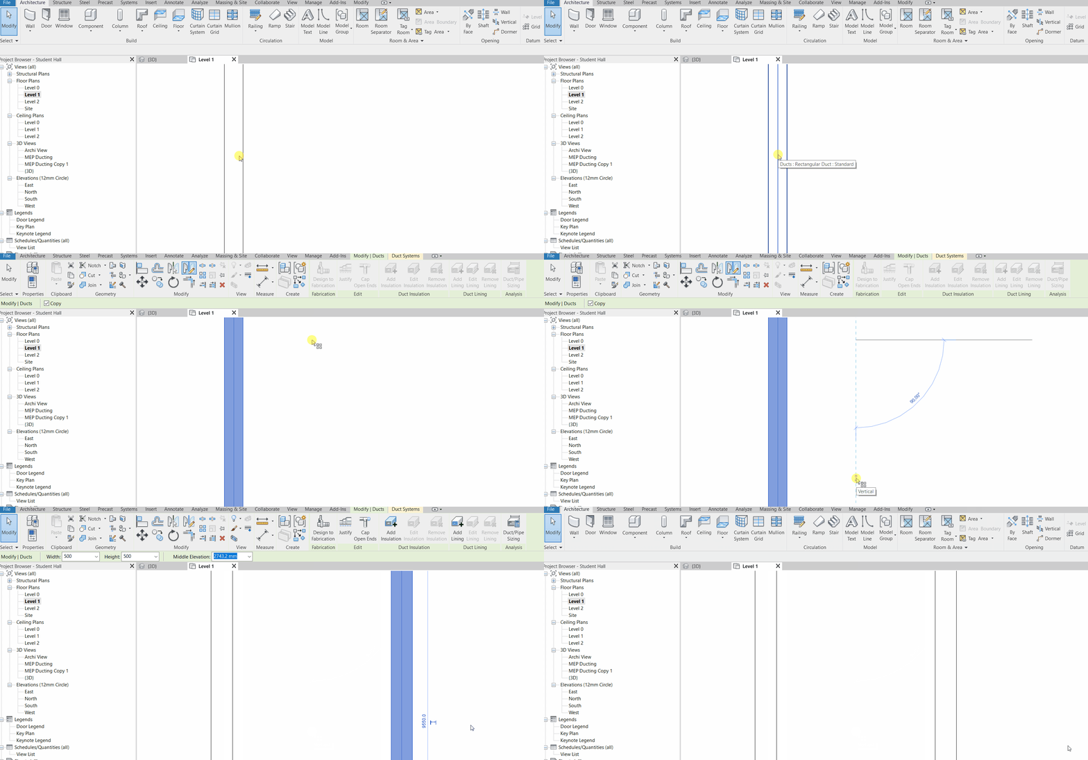
Split (SL) / Split with Gap
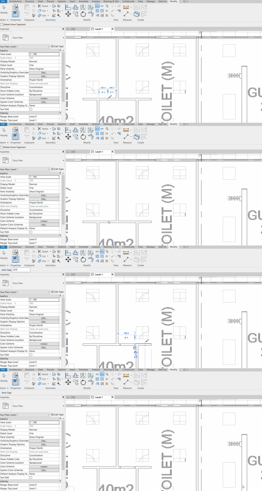
Array (AR)
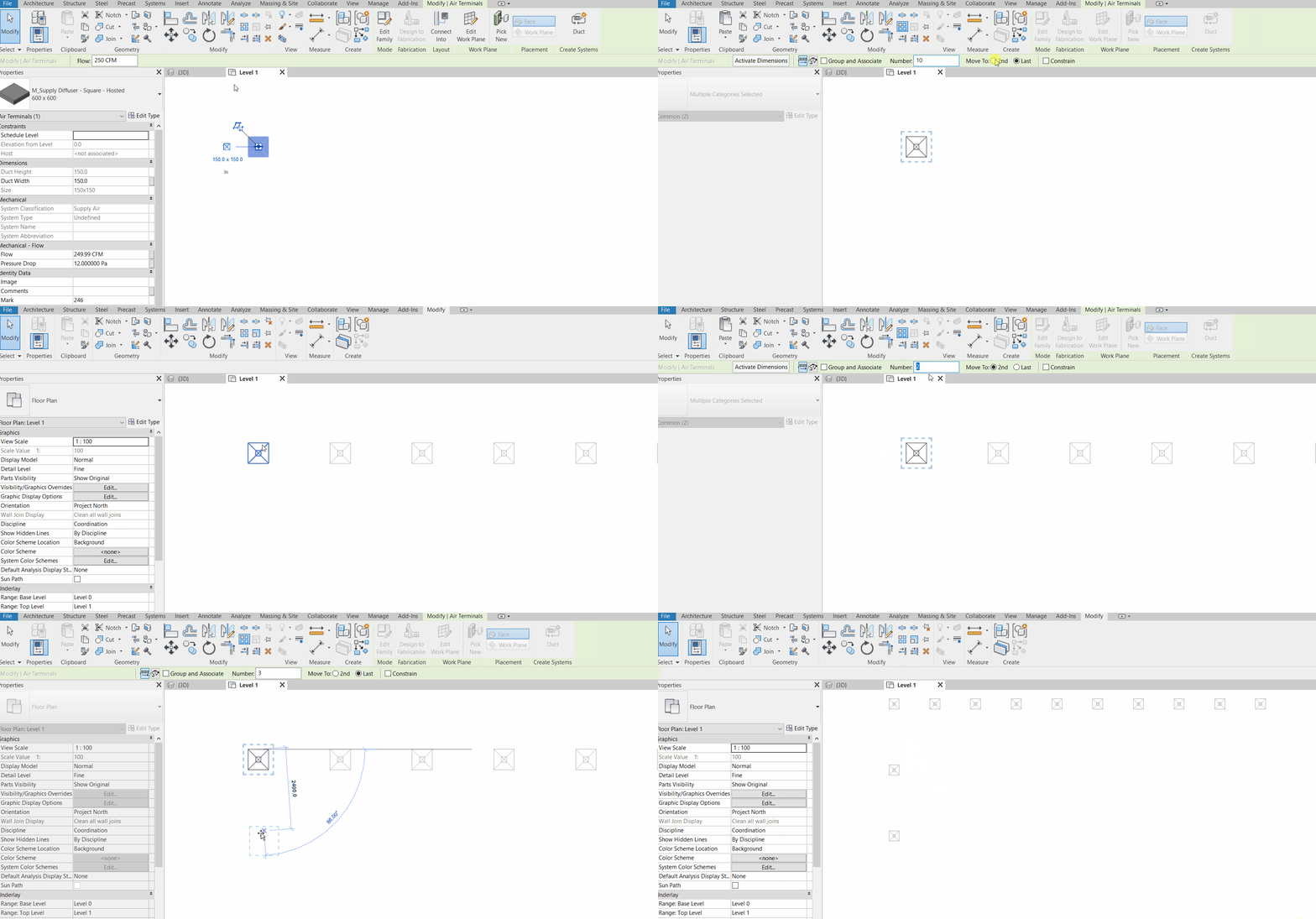
Scale (RE)
Import CAD
Importing CAD is slightly different from Linking, as Importing allows editing of the CAD file through Revit. To do so, firstly, go to the Insert Tab, and then click “Import CAD”.

Navigate to the CAD file we want to import, then click “Open” (take note of the few Import settings below)

You shall see your loaded CAD once you have imported. If you don’t see it, try double click the scroller of your mouse to zoom out to locate the imported items. Now, you may start to reconstruct all the elements from CAD in Revit (using pick-lines) including – reconstructing the Grid Lines, adding components such as columns etc. Before that, if you need to make adjustments to the imported CAD, you will need to unpin the item first.

You may use the “Query” function to check the properties (such as Layer, Block name etc.) for any imported element.

Model-in-place a Component
Sometimes, to add a component which is unique to the project, we can model the component in place. One example is an odd-shape structural support.

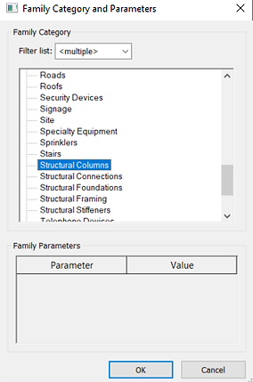
Select the right family category (in this case, Structural Column), click “OK”, and then give the new element a name. In the family editor, use Extrusion or other “Creation” tools

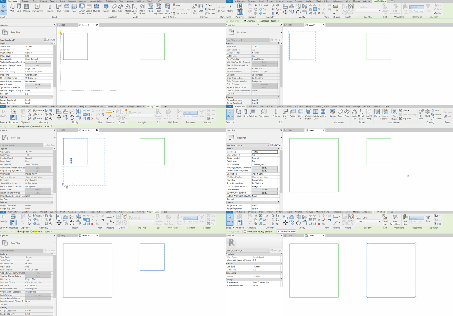
Use “Pick-Lines” or just “Lines” to define the boundary for extrusion, enter the end extrusion height, and then click on the green mark to extrude.

To edit the material, go back into the Editor by clicking “Edit in-place”, and then by the properties pane, Structural Material. Select the material from the material browser.


Visibility Graphics (VG)
Use the keyboard shortcut “VG” to run this command. “VG” sets the Visibility of all elements unique to each view. It is acting like turning off displays of layers in AutoCAD, but it can do more than that.
This is done by checking and unchecking different objects based on their categories. We can also set the transparency of those objects for coordination purposes. As mentioned, these adjustments are specific/unique to each view. For example, turning off “Walls” in the 3D view does not mean turning them off in the Plan or Elevation View.
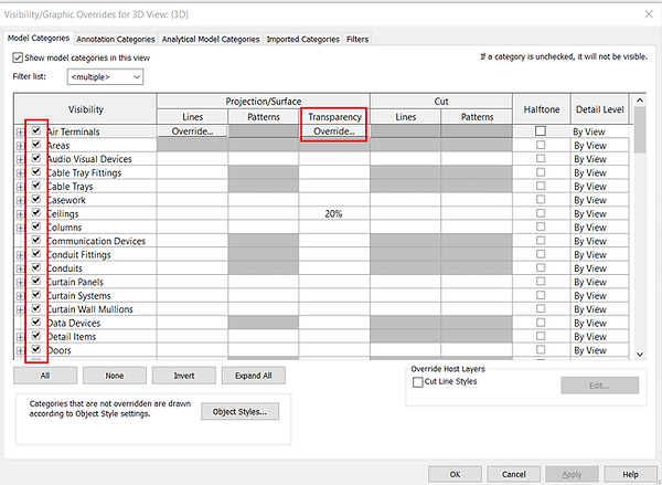
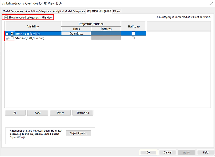
Imported Categories and Filters (next section) can also be selectively “turned off”
How to use Filter in Revit
Using Revit Filters may seem to be complicated, but it is actually straightforward. A Revit filter is a customisable set of conditions that tells Revit’s Visibility Graphics what to show and what to hide in a view. To add a filter, use the command “VG” for Visibility Graphics, then go to the “Filters” tab. Click “Add” and “Edit/New…” to create a new Filter.
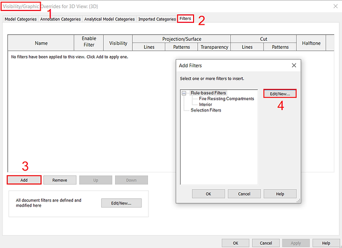
The added filter shall appear at the space on the side. Underneath the space there are 4 buttons to “Add”, “Duplicate”, “Rename” and “Delete” the filter.

ACMV consists of 2 major trades Air-Conditioning (AC) and Mechanical Ventilation (MV). It is normal for us to split each of these trades into a separate drawing. Hence, in the example shown below, we want to create 2 views – the first is a view with Air-Conditioning (AC systems) only, the other is a view with Mechanical Ventilation (MV systems) only. In both views, we want to eliminate fire-related systems such as smoke spill and pressurisation systems.
Therefore, we create 2 Filters.
The first filter, when unchecked in the visibility option, filters away all AC objects (Not Exhausts) or fire-related systems (Smoke Spill or Pressurisation), hence retains only all MV systems.
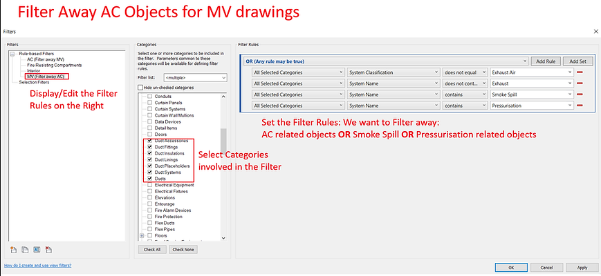
The second filter, when unchecked in the visibility option, filters away all MV objects or fire-related systems (Smoke Spill or Pressurisation).
To show a bit of complex applications of filtering, we add another “AND” condition for the filter to be applied. We apply the filter only when the second condition is also met: i.e. objects are not marked with the text “Heater Coil”. In other words, we would like to retain all objects which we marked as “Heater Coil” in the AC drawing. In certain cases, these added “markers” in the comments of an object to help in the filtering.

(Note: For “AND”, All Rules within the set must be True. For “OR”, Any of the Rules may be True)
Once a filter is created, we can add it as an item into the visibility graphics with the following steps: (1) Click Add to input a Filter; (2) Select from the Filter List the Filter that we just created; (3) Click OK; (4) Click Apply; (5) Click OK
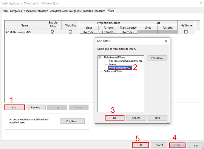
Now, added filters just become an option like any other categories, whose visibility can be turned on and off by checking and unchecking the option as shown below. To edit a filter, simply select any Filter, and then click “Edit/New…” to go back to the Filters Editor.

Project Unit
To change Project Unit, go to Manage > Project Units (Keyboard Shortcut: “UN”)

Drawing ACMV Ducts in Revit
Drawing duct networks in 3D can be frustrating for first-time user, but will be much easier afterward (compared to using most conventional 2D software). Therefore, it is definitely worth investing some time to learn and master this skill – one which has already been set on track to revolutionise the construction industry – for our own satisfaction (to just be able to draw and see in 3D), not to mention other advantages offered by 3D perspectives: visualisation and presentation, coordination, computation and analyses etc. that Revit offers as its all-in-one package.
The guide below targets to simplify all steps needed to draw a complete duct network in the shortest possible manner. By the end of this compact session, we will be able to draw a duct network complete with fittings and terminals as shown in the photo below.
Step 1: Set the View’s Detail Level
Firstly, I prefer to set the view’s detail level to minimally “Medium” in order to see 2-line ducts (this applies to all views in Revit). This is done by clicking on the “resolution” icon on the bottom left corner.

Step 2: Set Routing Preference
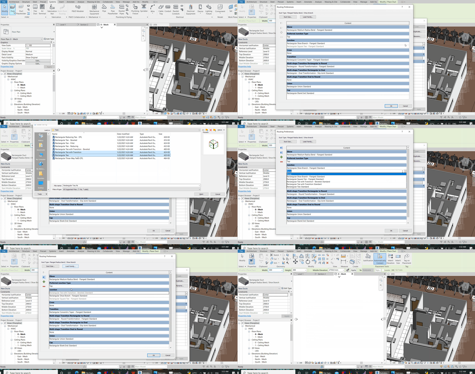
The next step is to define the routing preferences. To do so, simply type the command “DT” (stands for Duct), and then at the properties pane, click “Edit Type”. (If you don’t see a properties pane, go to “View” tab > User Interface > Check “Properties”)

Then, in “Type Properties”, select “Edit” Routing Preferences:

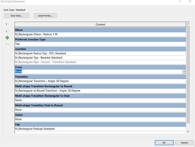
Next, from the “Routing Preference” window, we need to select and assign a Revit Family File (RFA file) for each type of the fittings, if there is no selection option in the drop-down list, we will need to load the Duct Fitting Family.
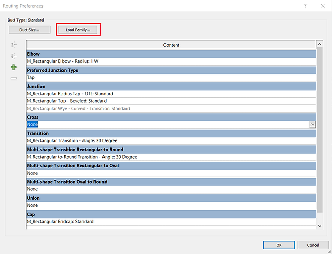
To load family, while selecting the type of fitting, click “Load Family”:
Then, navigate to your file directories to load the fitting families. Different types of fittings shall be available online. Your libraries for RFA files shall be available in your local PC, unless your Revit is a trial version, or unless you have missed installing the contents when you install Revit. Nonetheless, you may always visit Revit’s Content Download Site to download the entire libraries.
From the Revit official webpage above, Select the Revit Content Installer of your preferred language to download. Then, run the installer with administrator to install required libraries. As shown in the photo below, the table in the page indicates the file location to retrieve the RFA files once they are done installing. For example:
Imperial: <Content Path>\Libraries\English-Imperial\
Metric: <Content Path>\Libraries\English\US\
Note that “<Content Path>” above indicates the destination for the installation of you Revit software program files (which you have defined during your Revit installation). If you did not change any setting, the file location shall be defaulted to (C:\ProgramData\Autodesk\RVT <Version>).
e.g. – C:\ProgramData\Autodesk\RVT 2022\Libraries\English-Imperial\.......

Navigate to the above-mentioned, your Revit’s <Content Path>, followed by Libraries, all the way to the RFA files as shown in the photos below. This file location may vary depending on where you install the contents into during your Revit installation. An example of directories is as follows:
C:\ProgramData\Autodesk\RVT 2022\Libraries\English-Imperial\Duct\Fittings\Rectangular

Alternatively, you may directly download the fittings provided in the zipped file below. (Note that it is always a safer practice to download from official Revit sites)
Zipped File for Duct Fittings RFA
Once loaded, you will be able to select the loaded family from the drop-down list for each type of fittings (see Picture below). Take note that a “Transition” fitting will only show up in the “Transition” section only, as defined by the family category, so does any other types of fittings. This is the reason why the RFA files are by default organised into folders according to the fitting types. You can click the “+” button to add more selection to the routing preference, and use the arrow to adjust the priority level of preferences of a fitting. The higher-up preference will be adopted first when those fittings are available based on various constraints.
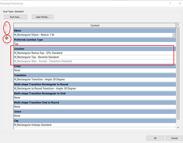
As a reference, picture above (summarised below) are some of the fittings that are most commonly needed in a rectangular duct network.
-
Elbow – 90 deg Smooth Elbow (1.0W)
-
Junction Type – Tee / Tap
-
Junction – Round Bevelled Tap Take-off (Tap) / Rectangular Bevelled Tap (Tap) / Rectangular Wye – Curved with Transition (Tee)
-
Transition – Pyramidal Transition
-
Cap – End Cap
Below are some illustrations for better recollection of these common fittings you certainly have seen before.
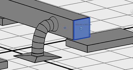
Cap – End Cap

Round Bevelled Tap Take-off

Rectangular Bevelled Tap
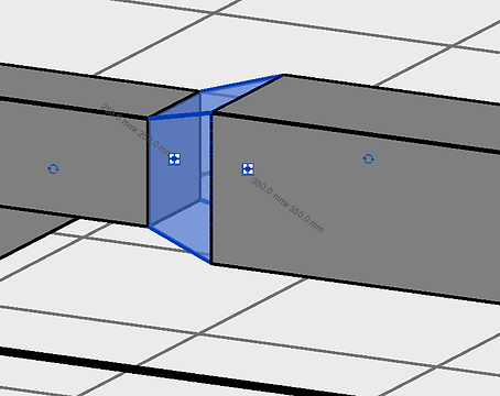
Pyramidal Transition

Rectangular Wye – Curved with Transition

90 deg Smooth Elbow (1.0W)
A few more things worth taking note include the smooth elbow turning radius (which defines how sharp or how smooth the turning of an elbow is), and the interchangeable selection between “Tap” and “Tee” fittings.
Smooth Elbow Turning Radius

525/350 = 1.5W
350/350 = 1.0W (Sharper turn, higher loss, less space is required)
700/350 = 2.0W (Smoother turn, lower loss, more space is required)
On a side note, referring to the picture below, you may need to interchangeably use the routing preference between “Tap” and “Tee”, and change the Junction accordingly.

Step 3: Start Drawing a Duct
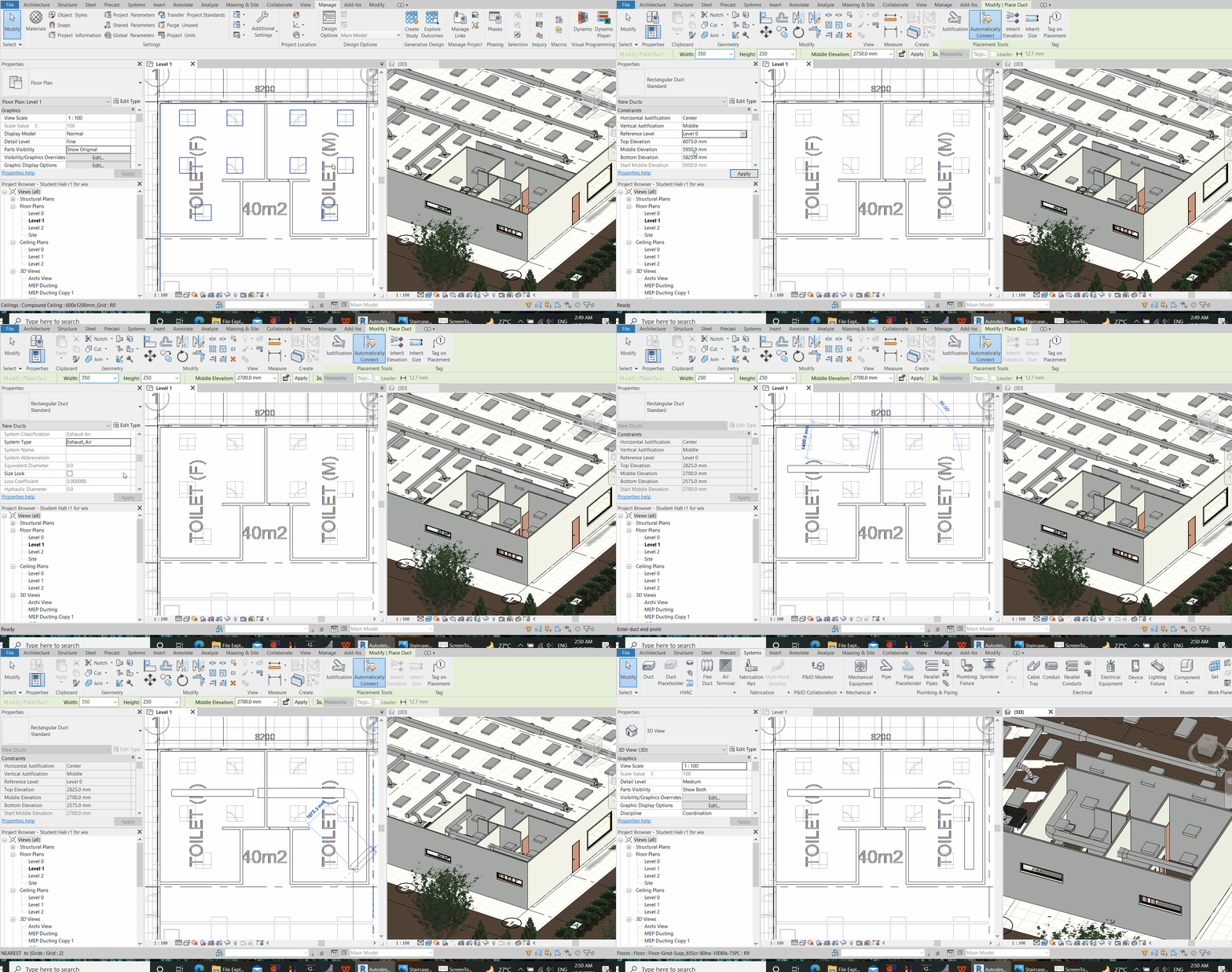
After the routing preference is set, it is time to start drawing. Use the command “DT” (stands for duct), and key in the required duct size and elevation. Middle elevation in this context, literally means the height from your reference level – depends on which level you set this to – to the middle of duct.

When 2 ducts join, the fitting from the preset routing preference will be inserted automatically, as long as the function “Automatically Connect” is opted (shall be opted by default).
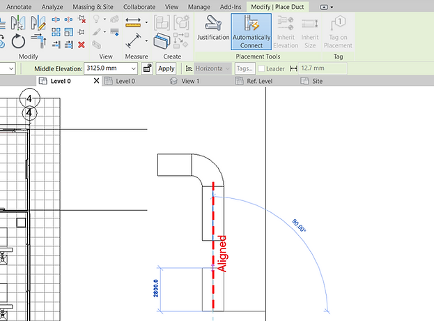
Ducts may not be able to connect when they are off-alignment. Type the “AL” (stands for align) command, then click the destination/reference duct center line, followed by the source duct center line to align the 2. Revit may allow auto-generation of ducts that run diagonally, but will also require enough space for that.
Sometimes, two ducts of different elevations (different levels) cannot be joined be (prompted with all forms of messages) due to the limited space for the installation of fittings – always note that fittings such as smooth elbows require space. Distance out the 2 ducts by setting the higher duct at a higher elevation and the lower duct at a lower elevation, to allow for more space for connection. Then, after a connection is made, readjust to desired elevations. We may then change the radius of the elbow from a smoother elbow to a sharper elbow to save some space after the connection is made.

It is best to refer to the 3D window on a separate screen to see in 3D, the duct network updated in real-time. This helps us better understand what has happened, and whether what being drawn is what we wanted.

If ducting drawn is not shown (cannot be seen), try the following
1) Ensure Ducting is turned on in Visibility Graphics (Command “VG”). Make sure ducts and fittings are checked, and turn off elements that might obscure the ducts such as roof or slab above.
2) In the View Properties Pane (press ESC – to deselect any item), set the discipline to “Coordination”
3) It is easy to visualise all constructed works in a 3D view window by the side of your plan, so you will know what is going on.
4) Set the Elevation of the duct and check whether the View Range (Command “VR”) of the View encompasses it. Make sure you add the duct in the correct plan view, at the correct level.
5) Check the Revit Filter settings to rule out any desired parts being selectively filtered out.
Step 4: Continue drawing the Duct with the fittings auto-generated from the routing preferences
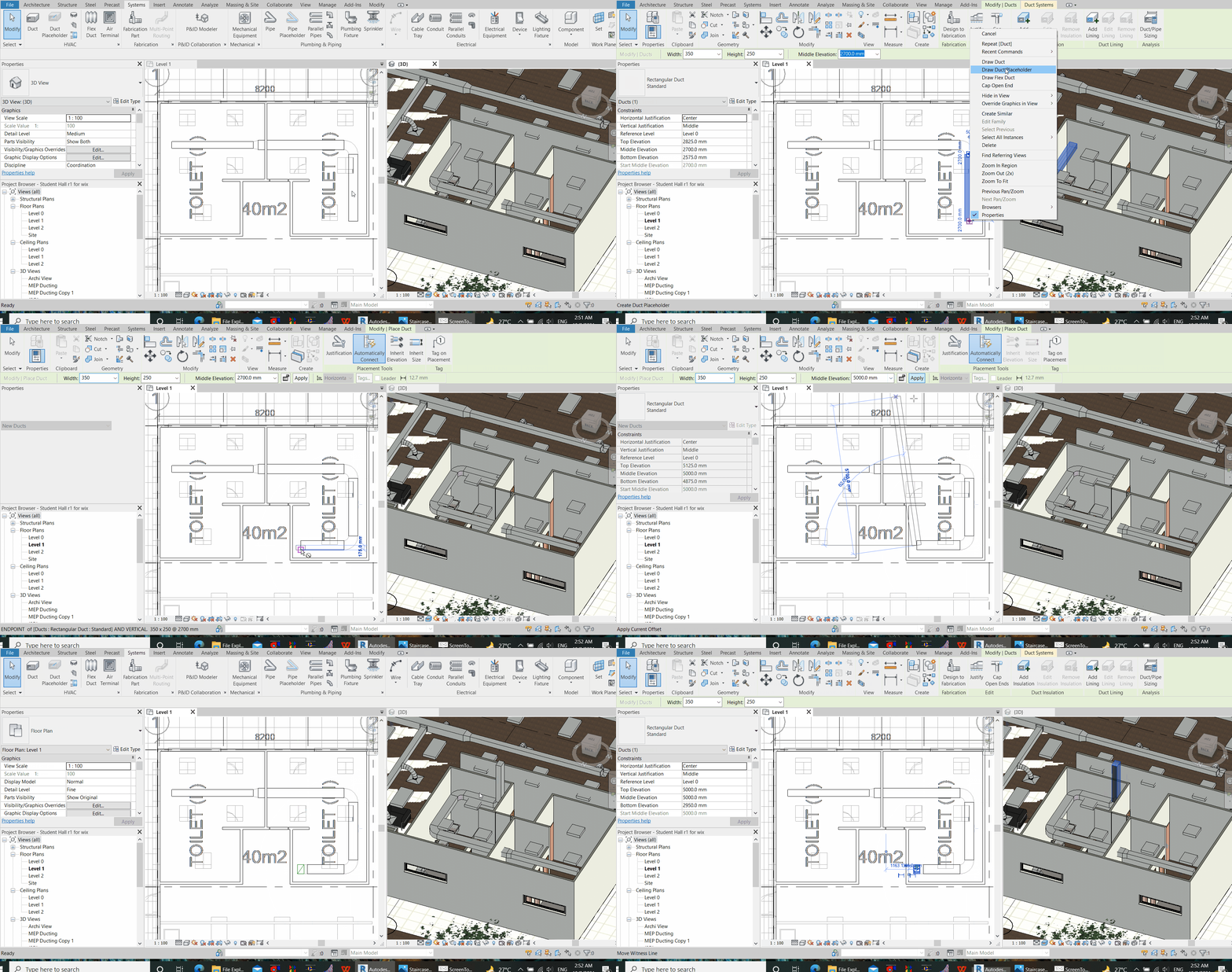
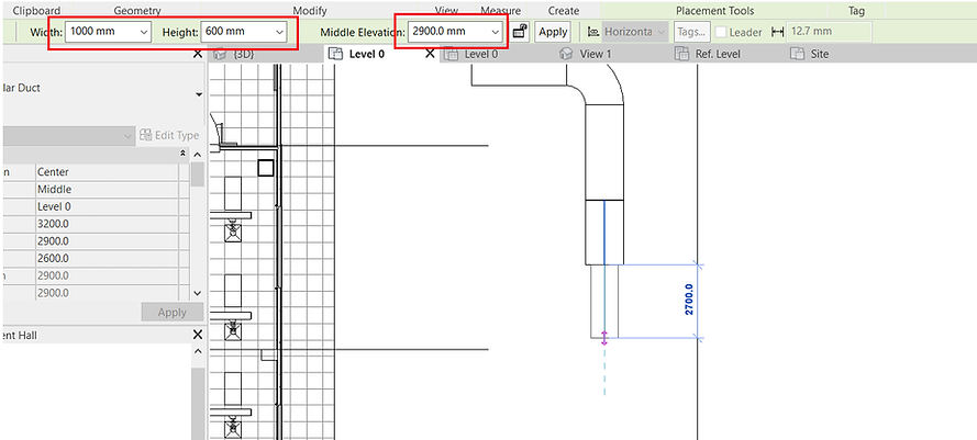
For a duct transition or change in duct elevation (Rise or bend up or Down), we just alter the parameters in the ribbon below, continuously, without the need to hit ESC. However, strangely, Revit requires the user to retain your cursor within the box indicated below when you type your figures in.
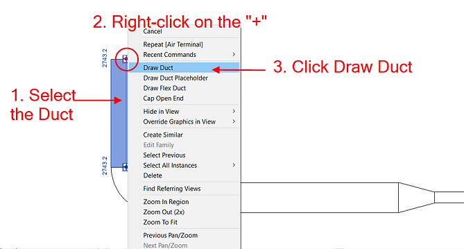
If you have hit “ESC”, to continue drawing from an existing duct, (1) click on the duct, and then (2) right-click near the “cross” icon at the “to-be-extended” end, and then (3) click “Draw Duct”.
Three buttons in the ribbon shown below are commonly useful, where pushed down
-
“Automatically Connect” gives Revit the permission to perform all connection where feasible, including the deployment of fittings defined in the Routing Preference.
-
“Inherit Elevation” tells Revit to automatically assume the duct middle elevation in line with the duct it is connected to.
-
“Inherit Size” tells Revit to automatically assume the duct size in line with the duct it is connected to.

Step 5: Air Terminals
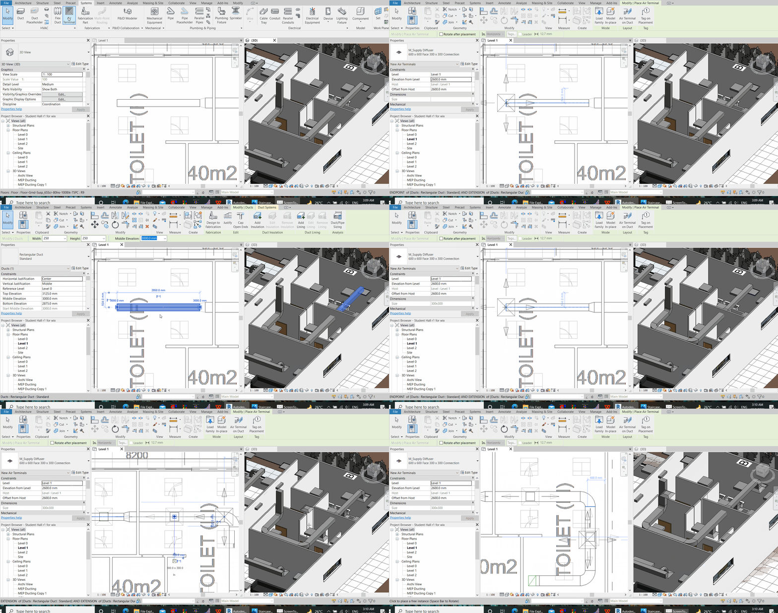
To add air terminals, such as air grilles, louvers or diffusers, (1) type the command “AT”. From the properties pane on the left, (2) select the type of air terminals that you want to add and, (3) input the elevation of the air terminal with the base at the reference level. This is often the ceiling level with respect to the finish floor level.

Then, hover the previewing air terminal to where you want to place it in the reflected ceiling plan. Click to register it in any previewed spot. Then, use a flexible duct to connect from a rectangular rigid duct to the center of the air terminals. If you are to connect from a rigid duct directly to the air terminal (without a flex duct), make sure to align the center of air terminal with the center of duct, by using the “AL” (stands for Align) command.
Step 6: Draw a duct Vertically
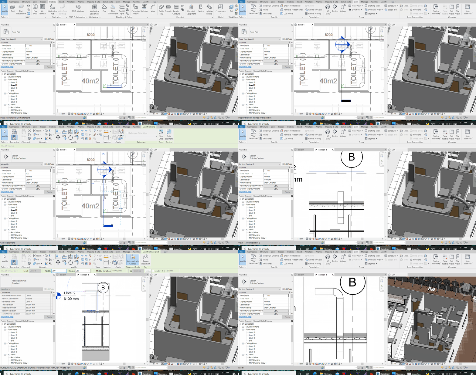
Then, hover the previewing air terminal to where you want to place it in the reflected ceiling plan. Click to register it in any previewed spot. Then, use a flexible duct to connect from a rectangular rigid duct to the center of the air terminals. If you are to connect from a rigid duct directly to the air terminal (without a flex duct), make sure to align the center of air terminal with the center of duct, by using the “AL” (stands for Align) command.
If you cannot see what you want to target at in the added section, make adjustments through the control methods below. First click on the added Section, then:
-
Grip and hold the four-directional “Move” icon to move the section around.
-
Toggle the view direction by clicking on the 2-directional arrow icon
-
Adjust the view depth of the section by holding down the arrow and dragging the arrow on the box. You may want to reduce the view depth of the Section to exclude all non-targeted components, which may add to your confusion when you perform a connection.

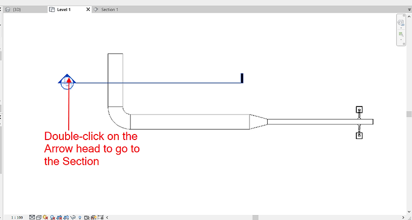
Then, Double-clicking on the Arrow to go to the desired Section. Set the Detail level (Step 1) to at least “Medium”
Subsequently, draw the duct on the section, from the grille toward the duct. As mentioned, ensure enough space (marked “h”) to allow for duct fittings. Strangely, you may need to allow more space for “h” than you actually need. Therefore, you may reduce this allowance further (if needed to), after the connection (Allow for more “h” > Make the connection > Reduce “h” if necessary).
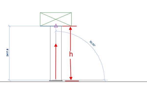
Step 7: Draw a Flexible Duct
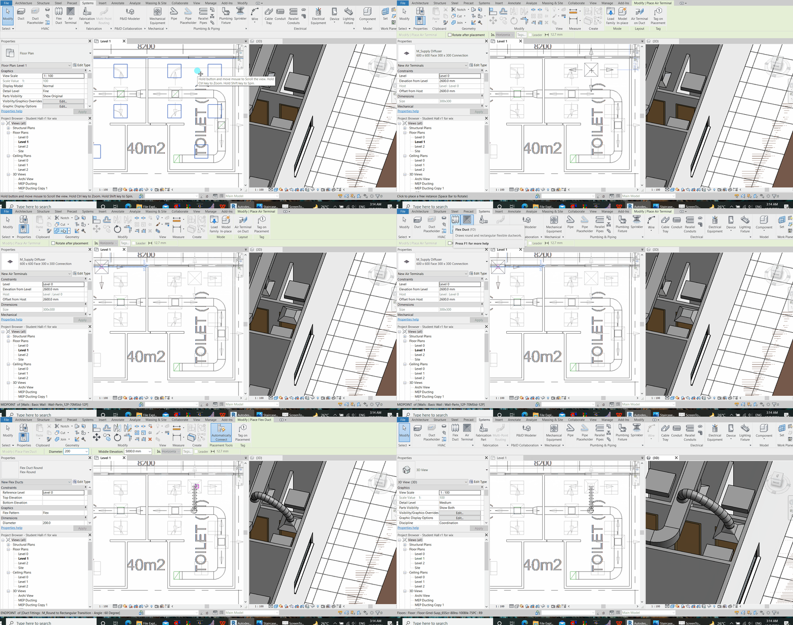
To draw a flexible duct, type the command, “FD”.
To set the routing preference for Flex Duct, click “Edit Type” on the Flex Duct Properties Pane.

If there is no option for the drop-down list, go to the Inset Tap, Load Family, and load the relevant round duct fittings into the project. An example of file location for the takeoff for flex duct can be found in the location below.
C:\ProgramData\Autodesk\RVT 2022\Libraries\English-Imperial\Duct\Fittings\Round\Taps

How to Generate a Duct Pressure Drop Report with Revit
This section will show how to calculate a duct pressure drop report using Revit. Note that the computation below only considers the external static pressure (ESP) for fan sizing, and do not consider the internal static loss such as filters within the air handler unit.
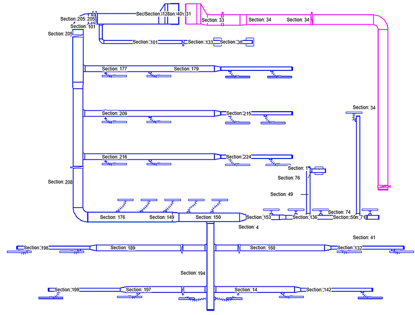
The first step is to isolate the ducting network. For demonstration purposes, I prefer to select the entire ducting network, then copy and paste to another empty Revit project. To select the entire duct network, hover your cursor over any point on the duct, hit the “Tab” kay repeatedly, and then click to register the selection preview. To add on top of this selection, repeat this step to select another network, but before clicking, hold on “Ctrl” to add on top of a registered selection.
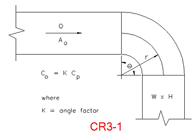
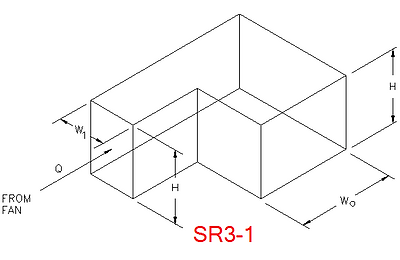
Subsequently, Revit usually sets the elbow loss method as SR-3-1 by default, which may not be applicable for radius elbows (the loss value has only very minimal changes between a smooth or a sharp elbow) under “SR-3-1” loss method setting. Therefore, I would usually prefer to use “CR3-1” as the loss method setting instead (if you are using a radius elbow).

To do this, select a fitting, and then at the properties pane, click “Edit” Loss Method setting. This will bring you to the window as shown above. Select “CR3-1” and then click “OK”.

At the time of this post, unfortunately, there is no way we can change the default settings, or select multiple fittings to change the loss method setting at once. The only way it can be done is to select and change one fitting after another, or we use Dynamo (involves Python coding).
This may sound discouraging (it does, at least to me initially), but having to change all elbows loss method one by one doesn't really take a lot of time as I initially expected. However, make sure all elbows in the system are updated (not just those along the critical path) because those may affect the total pressure drop for the critical path determination.
If you know programming, this is the file location for the XML file revit uses to assign and compute fitting losses.

Again, unfortunate enough, if you happen to update an elbow”s radius multiplier, you will also need to toggle the ashrae table settings (for example, from CR3-1 to SR3-1, and then back to CR3-1) in order that the updated loss value is registered in the system inspector and pressure drop calculations.
Next, you will need to make sure that your duct network is properly assigned in a correct system.
Select the entire supply duct network. Then, under properties, make sure the correct system is assigned. In this case, “Mechanical ACV – Supply Air Duct 1” is selected. Then, click “Apply”
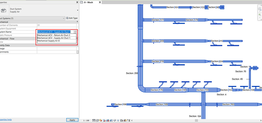
To select the system, click on the system (by hitting the “tab” key repeatedly and click when dashed lines are shown)

Then, go to the system inspector to inspect the duct system.

If you do not have the option for “System Inspector” or “Duct Pressure Drop Report” as shown above, there may be several reasons. Try the following:
1. It might be due to incomplete connectivity. Go to the “Analyse” Tab, and then click “Show Disconnects”. Fix the connectivity issues shown in yellow disclaimer icon. Disconnection at the end of the system is fine (such as shown below, at the termination end to the air handler unit).

2. The absence of the option for “System Inspector” could also be due to the assignment of system. Try to assign the duct network to a different duct system, say, the default air supply system for Revit and try again. Delete mechanical equipment which are of different systems from the connection (or copy and paste only the ducts to another workspace) to test separately. Always utilize the system browser to help identify your system

The System Browser is very useful to delete any system name. For example, when you have one fresh air system (cyan) connecting into return air system (magenta). We want to delete the fresh air system assigned to the short length of cyan duct, and in so doing, the fresh air duct will be automatically assigned with the rest of the system (return system)

To do so, hover your cursor on top of the segment of duct where you want to delete the assigned system, and then hit tab continuously until you see the preview for the selection of the system (take note: must be dotted line). Then click to register the selection.

On the system browser, the assigned system for the selected duct segment is shown. Make sure to expand the list fully, before right click and click “delete”

The duct with the deleted assigned system shall be automatically re-assigned to the system it is connected to, or it could become unassigned. You can also assign any ducting to a system by selecting them in the Properties Pane.

3. A very likely reason for “System Inspector” or “Duct Pressure Drop Report” to not show is due to your air terminals” parameters settings. Make sure your air terminals” direction are set correctly. Go into the family of your air terminals and try to toggle the direction of flow (Refer subsequent step). Always make sure to imagine your air flow along the ducting network is valid (not bidirectional), and flow configuration to be “preset”.

In the System Inspector, click on “Inspect”, and hover your cursor to wherever you want to inspect. The System Inspector will show important information such as flow, and pressure drop. You can also see the direction of flow of air in arrows, and in red arrows, Revit indicates the critical path with the highest pressure drop. When done, click “Finish” (Green Tick). (Note: There must be a reason why Revit assumes the Critical Path as it is. If you suspect the critical path is illogical, try to look for fittings with unusually high losses along the critical path, using the system inspector. If you are not able to tell from the system inspector, generate the loss report to read it. The end of this section will describe how to read from the generated duct pressure loss report.
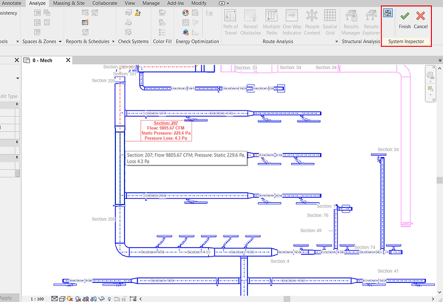
If you happen to see weird directions of airflow, you need to check all your air terminal’s connector and make sure the direction is set correctly. Double click on the air terminal to “Edit family”. In the family file, click on the connector (usually indicated in green as shown below)

Set the properties as shown below. Make sure you toggle the flow direction correctly if your system inspector shows otherwise. Set the flow configuration to “preset”.

Selecting “Calculated” may have the problem where you will have problem not seeing “System Inspector” or “Duct Pressure Loss Report”. As shown below, use a standard type of Air Terminal and the problem shall be resolved.

At least the following setting shall work, using a standard supply air grille (refer below)


When done, Load the updates into your Project (update parameters)

Go back to the system inspector to check if there is any more error. The system inspector is useful to check any other weird or exceptional readings along the network. Check for example, if there are fittings with exceptionally high pressure drops. They might just be some manual inputs that shall be corrected.
When there is no more error, select the system again, and this time, click “Duct Pressure Loss Report”

Then, in the pop-up window, select the fields you want to display in the pressure drop report, and click on the green arrow to the right to add selected parameters (red to remove). You can save this setting by assigning a name to it. After that, click “Generate”, and save the pressure drop report as a HTML format.

A whole list of pressure drops along all sections are displayed. Our interest is the Critical Path Loss, which are computed at the bottom of the sections” pressure drop list. This Critical Path Total pressure drop is the summation all the pressure drops along the route with the longest route (the worst case scenario)

You can either tell which section the list is referring to by checking in the system inspector, or simply, tag the duct with “Duct Sections”. Refer to “Annotate (Tag by Category)” and “Tag All” (Separate Guide). If you do not have a duct section tag, download the RFA file below to load into the project, or simply create one by copying any duct labels family, then edit the label to represent duct section (Refer Separate Guide - Annotation).
Zipped File for Duct Section Annotation RFA

There are 3 main tables in the pressure drop report:
1.
Example:

“The total pressure loss calculations by sections” indicates the total pressure drop for each section of duct from ducting, fitting, and air terminal. The end of this table indicates the critical path which is identified with the highest sum of the pressure drop among all other paths, indicated in Pascal.
2.

Example:
“The detail information of straight segment by sections” indicates the breakdown of total pressure drop due to linear length of duct-run for each section of duct.
3.
Example:

“Fitting and accessory loss coefficient summary by section” indicates the breakdown of the total pressure loss arising from each type of fittings in each section of duct. This table is useful to detect unusually high losses in fittings. For example, we can see from the table below that section 811, 813, and 814 has unusually high fitting losses from SR5-1. This can be further confirmed along with the system inspector. From the list below, we know that SR5-1 is a take-off branch. Strangely, for SR5-1, Revit assumes high loss coefficient when the take off branch CFM is much lower than main duct. In such occasions, we may want to set the loss method (ashrae table) to SR5-13 manually from the properties pane.

Some of the common fittings are as below
Round
CD3-6 Elbow, Pleated
CD3-9 Elbow, 5 Gore
CD3-10 Elbow, 7 Gore
CD3-12 Elbow, 3 Gore
CD3-13 Elbow, 3 Gore
CD3-17 Elbow, Mitered
CD6-1 Screen
CD9-1 Damper, Butterfly
CD9-3 Fire Damper, Curtain Type
ED1-1 Duct Mounted in Wall
ED1-3 Bellmouth with Wall
ED2-1 Conical Diffuser, Round to Plenum
ED5-1 Wye, 30 Degree
ED5-2 Wye, 45 Degree
ED5-6 Capped Wye, Branch with 45
ED5-9 Symmetrical Wye, 60 Degree
ED7-1 Centrifugal Fan
ED7-2 Fan Inlet, Centrifugal
SD2-6 Stackhead
Rectangular
CR3-1 Elbow, Smooth Radius (No Vanes)
CR3-3 Elbow, Smooth Radius (1 Vane)
CR3-6 Elbow, Mitered
CR3-10 Elbow, Mitered Single thickness vanes
CR3-17 Elbow, Z-shaped
CR6-1 Screen
CR6-4 Obstruction
CR9-1 Damper, Butterfly
CR9-4 Damper, Opposed Blades
CR9-6 Fire Damper, Curtain Type
ER2-1Bellmouth, Plenum to Round
ER3-1 Elbow, 90 Degree
ER4-3 Transition, Rectangular to Round
SR2-1 Abrupt Exit
SR2-3 Plain Diffuser
SR2-5 Pyramidal Diffuser, Free Discharge
SR2-6 Pyramidal Diffuser, with Wall
SR3-1 Elbow, 90 Degree
SR4-1 Transition, Rectangular
SR5-1 Smooth Wye
SR5-13 Tee, 45 Degree branch
SR5-14 Wye, Symmetical
SR57-1 Fan, Centrifugal
SR7-2 Plane Asymmetric Diffuser at Centrifugal fan outlet
SR7-17 Pyramidal Diffuser at Centrifugal Fan Outlet
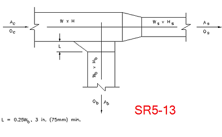
Additional Notes to Consider (as of the date of this publication):
1. Revit ignores transitions with very little difference in sizes (negligible angle)
2. Revit does not allow default settings of loss method. We need to specify the ashrae table setting for each fitting one by one. For smooth elbows, most shall be manually set from SR3-1 to CR3-1.


3. Some inconsistencies are observed where Revit may set shoe tap (beveled tap) take-offs as Y junction SR5-1, SR5-13 & SR5-11 by default. SR5-1 (usually higher loss) sometimes gives strangely high loss coefficient when take off branch CFM is much lower than main duct. Only in such occasions, Ashrae table setting is manually set to SR5-13.


4. Changes in fitting losses, such as a change from “sharper” elbow to “smoother” elbow will only be updated in the calculation when the ashrae table setting is toggled to another, and then back to the original.
5. If you get extremely huge losses. Go to Windows > Control Panel > Region > Additional settings
Make sure to set a dot (".") for decimals (See Reference)

How to Export to Navisworks (DWF)
In your 3D view window, Go to File > Export > DWF/DWFx

Ensuring 3D view is used in the preview, click “Next”

Select a destination folder and save the file as “DWF Files”

Add Landscape, Site Ground and Topography
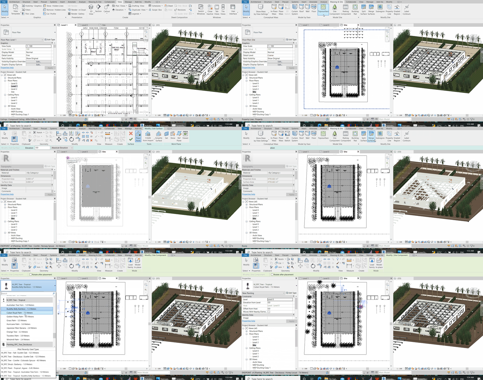
Go to the Site View in Project Browser (1). From the “Massing & Site” Tab, click Toposurface (2) – then place points (3) – After entering the site elevation (4), mark on the site plan the boundary for the selected elevation (5). Then, repeat for the other elevations.

To edit surface of topography (add grass, for example), select the added topography and click “Edit Surface”

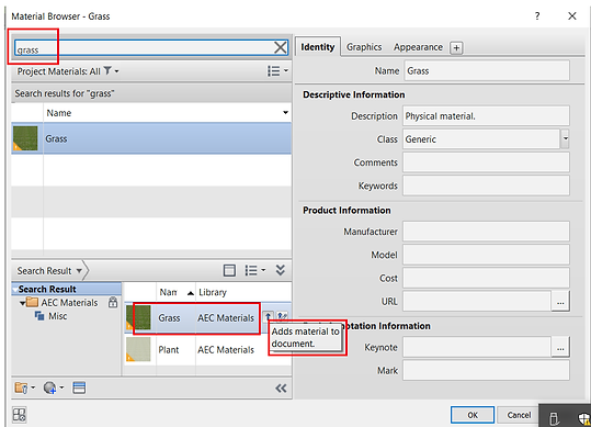
Then, click material selection and search for “Grass”, and “Adds material to document”.

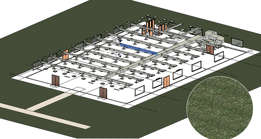
Use “Subregion” to add different surfaces on top of another.
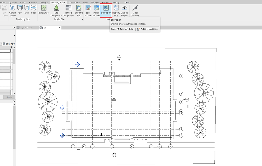
Use Site Component to add Trees and Bushes. Again, load family to add to the variety of options.

Monitor the addition of landscape through the 3D view.

Adding Furniture
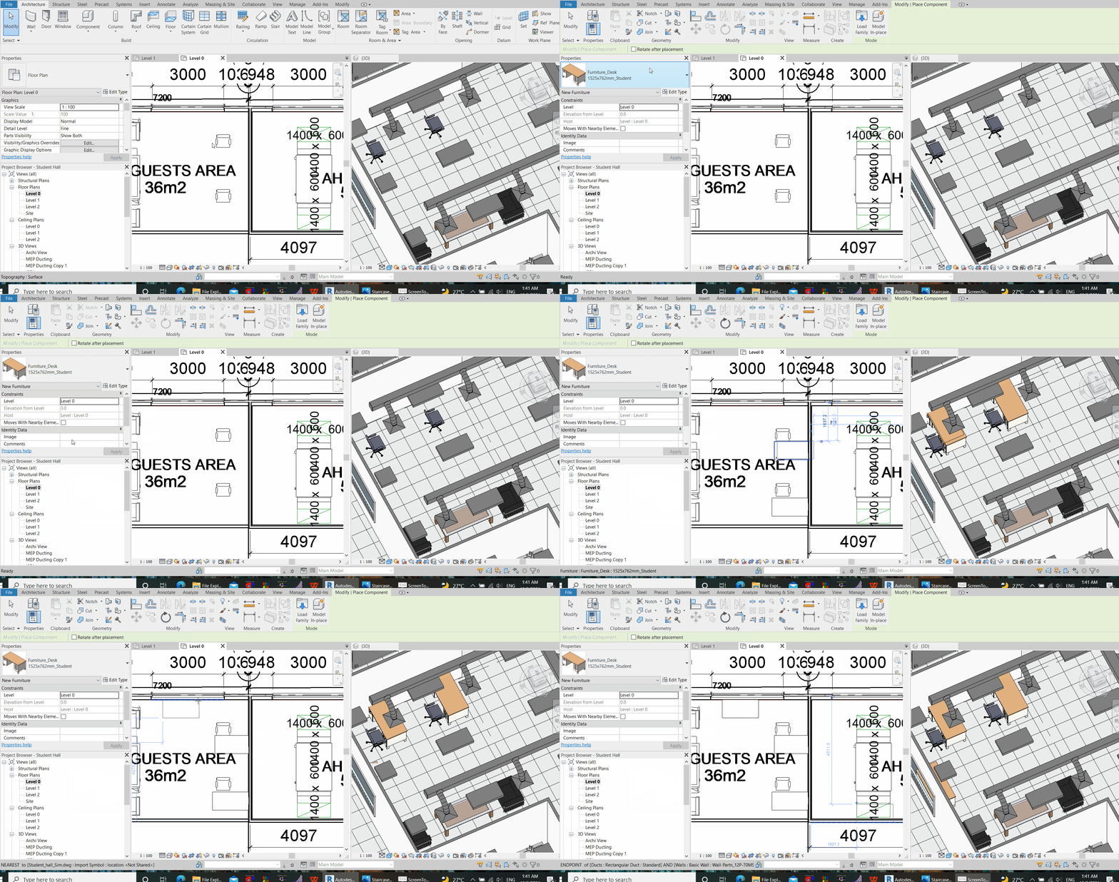
Other items such as Furniture & Fixture, Sanitary and Plumbing fixtures fall under Components (Keyboard Shortcut: “CM”). After a selection is made, simply click on a location on plan to register the preview. Prior to that, use the space bar to rotate the fixture in the preview mode.
For the fixtures, you may model a family file on your own, download it from any available, trustable sources, or retrieve from Revit’s standard libraries.
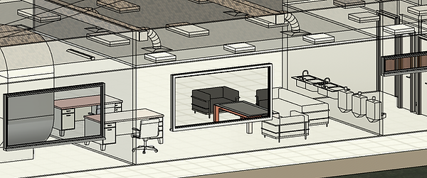
Adding Walls
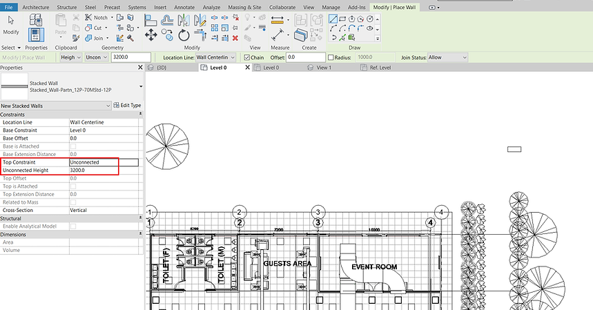
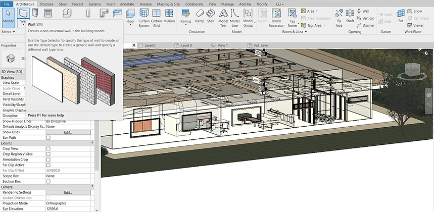
Use the keyboard shortcut “WA” to add walls. On the plan view, draw the walls by defining the wall’s height and the wall’s top constraints.
Adding Doors and Windows
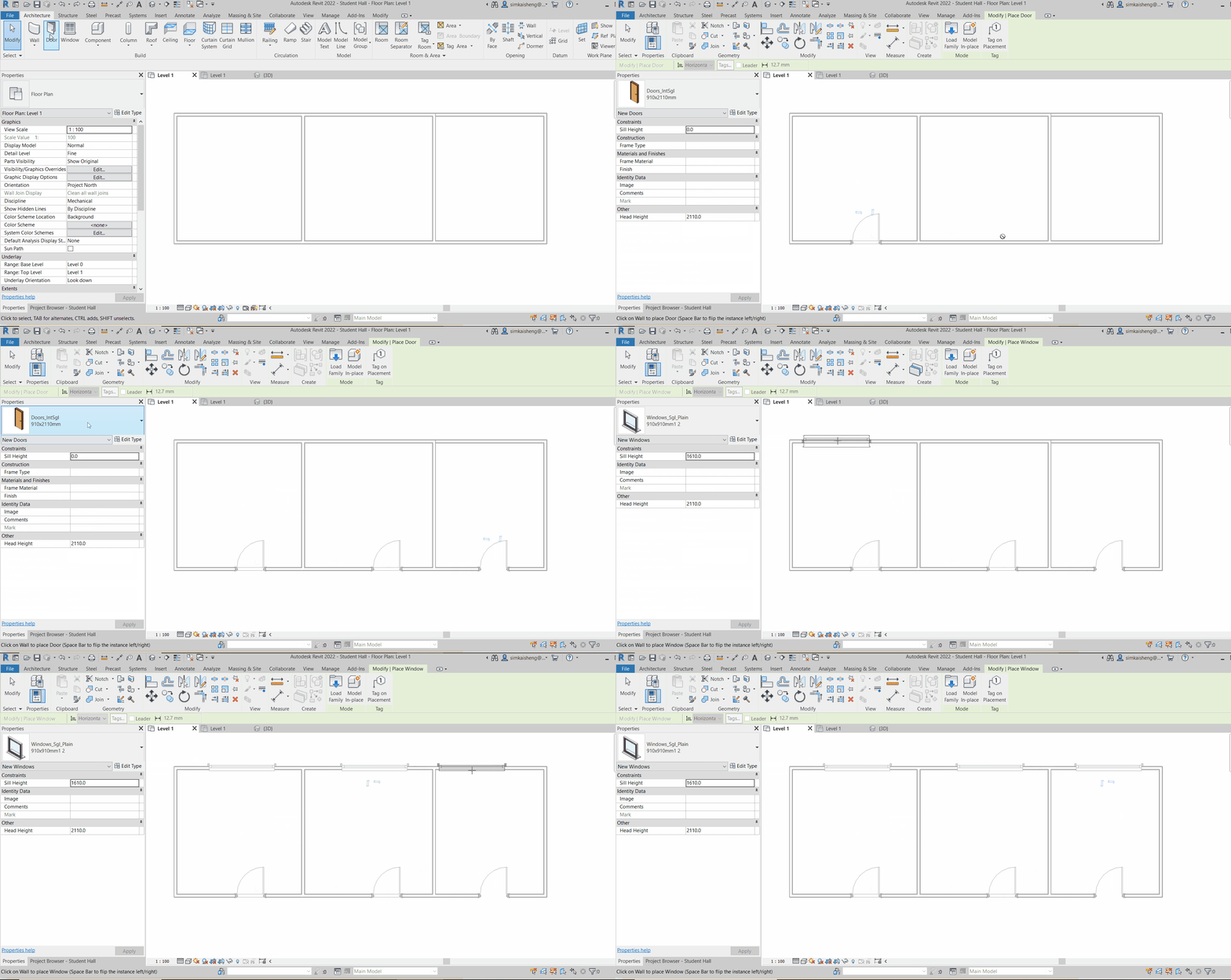
Use the keyboard shortcuts “DR” for door and “WA” for windows. Hover your cursor to where you want to add the door or window along a wall. With the base constraint and base offset defined, click to register the preview for where you want to add door or window. Repeat for another, without the need to press “ESC” in between.

Adding Floor Slab / Ceiling / Roof
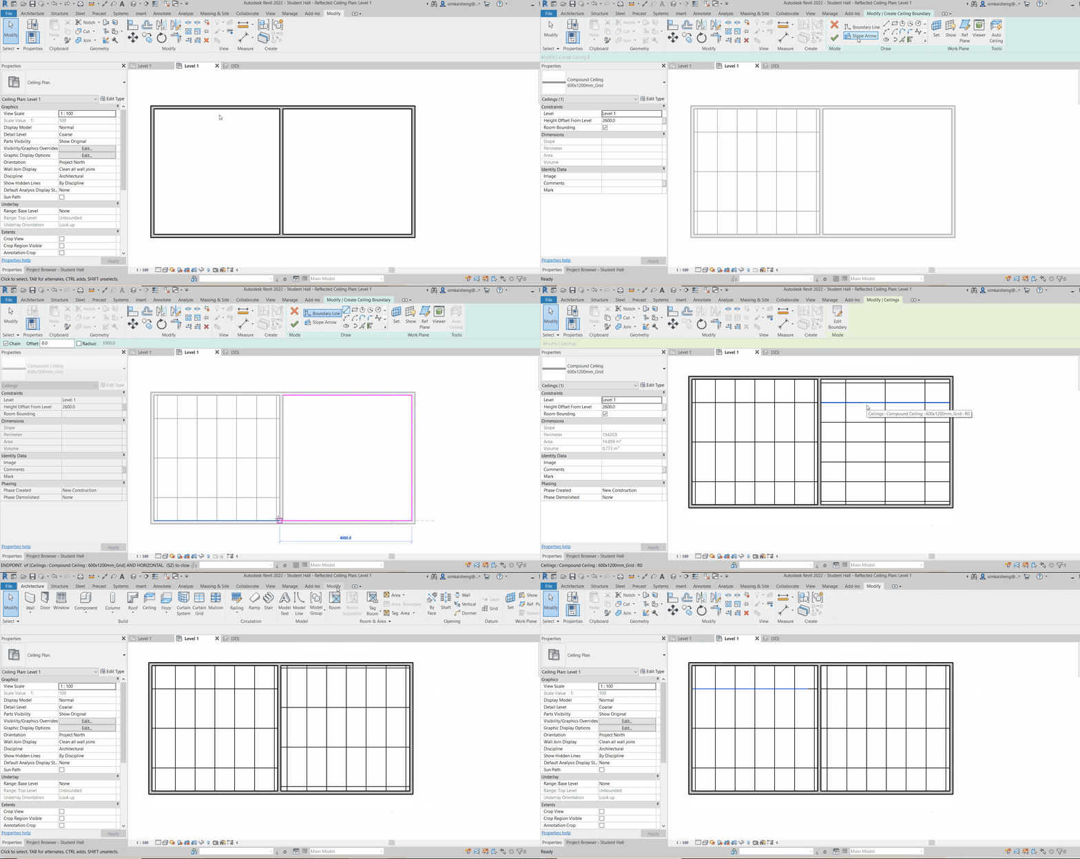
The concept of adding a floor slab, ceiling or roof is similar in Revit. Go to Architecture > click Roof, Ceiling or Floor

Subsequently, draw the boundary of the roof / floor / ceiling, followed by a click on the green tick to confirm. Make sure the boundary is completely enclosed and does not have overlapping lines. Otherwise, Revit will prompt an error message. When this happens, click “Show” usually navigates to the specific area where the error lies.

Adding Floor Tiles
To add floor tiles, we need to first select the floor. Utilise settings in the Visibility Graphics to hide away walls or roofs that may be blocking our selection. Then, click “Edit Type” in the properties pane, followed by “Edit Structure”.

Next, Select Finish Material from the “Edit Assembly” Windows.
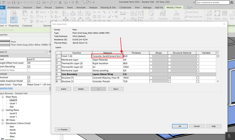
Navigate to and select a desired Ceiling Tiles’ material, size and types. If there are no floor tiles, ceiling tiles will do equally well

Apart from the floor finishes, we may also edit materials selections for the intermediary layers below the finish floor.

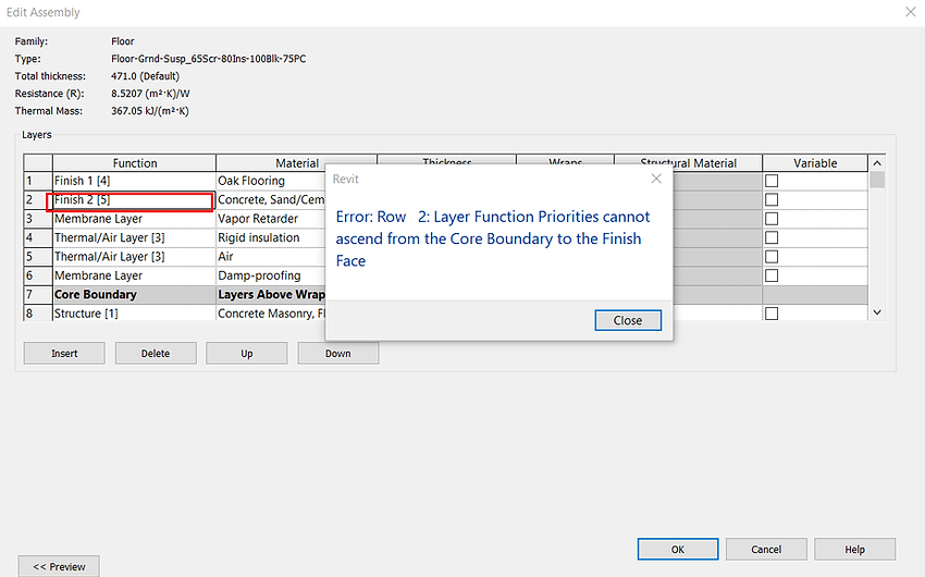
If an error message prompts below, try change the function of the affected layer to other functions (such as Finish 1)
Annotation (Dimension)
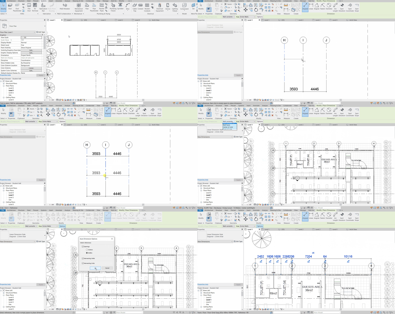
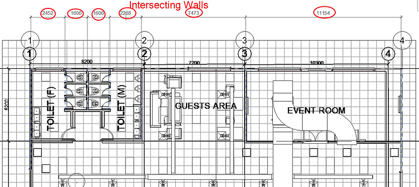
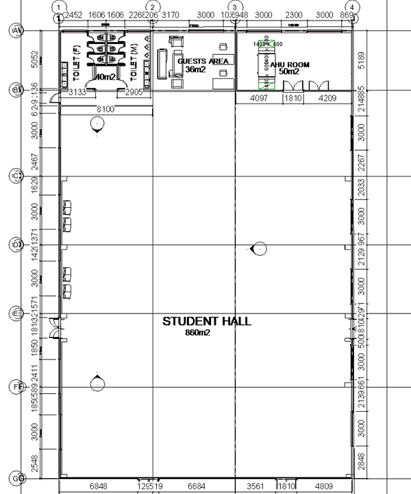
Revit enables easy annotation that spares the need to annotate individual references. In other words, Revit can for example, annotate the dimensions for the entire selected wall at one go, based on measurement preferences, be it
-
Opening widths
-
Intersecting Walls
-
Intersecting Grid
-
All of the above



The above preferences can be performed based on the following measurement settings
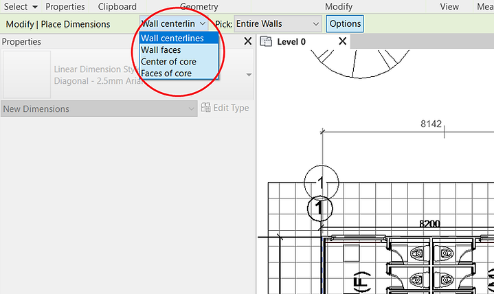
This function enables annotation to be done fairly quickly
Annotate (Tag by Category)
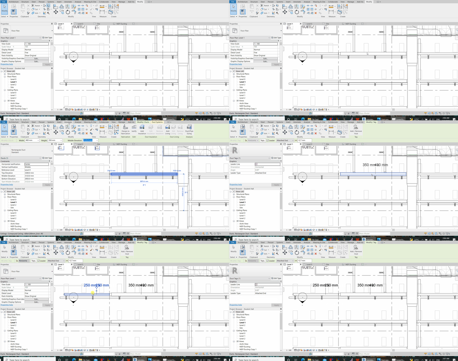
Revit enables rapid tagging of specific parameter, such as duct size, grille size, bottom of duct, airflow per grille, etc, with one click for all tagging.
Let us try out an example to annotate duct sizes.
Firstly, go to the annotate tab and click “tag by category (or Keyboard Shortcut TG)”, then click to select any duct segment to annotate.

For this first time, Revit will prompt you to load a tag. This tag defines the style of your tagging. Click “Yes”.
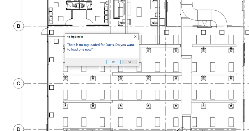
Try to look for the family file for Annotations, in this case, duct size. If you cannot locate the family files in your Program Files, download the zip files below. The family file shall usually be located at
C:\ProgramData\Autodesk\<product> <release>\Libraries
Zipped File for Duct Size Annotation RFA

Then, hover your cursor to a duct where you want to annotate and click on it.
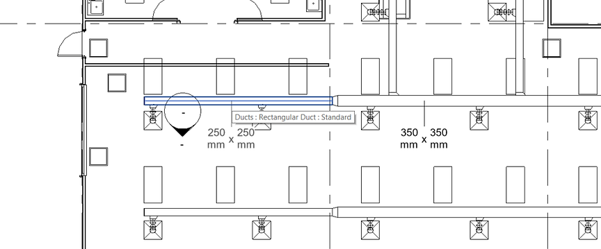
To change the style of the Duct Label, click on any tag, and then click “Edit Type” on the Properties Pane.

Exercise 1
For example, we want to make a few changes to the duct annotation to be as shown in blue below
-
to remove the leader line and to have the annotation sticked onto the duct surface without any offset
-
to change the label text colour to blue
-
to remove the “mm” unit from the annotation
-
to interchange the parameters from “height x width” to “width x height”

(1) to remove the leader line and to have the annotation sticked onto the duct surface without any offset
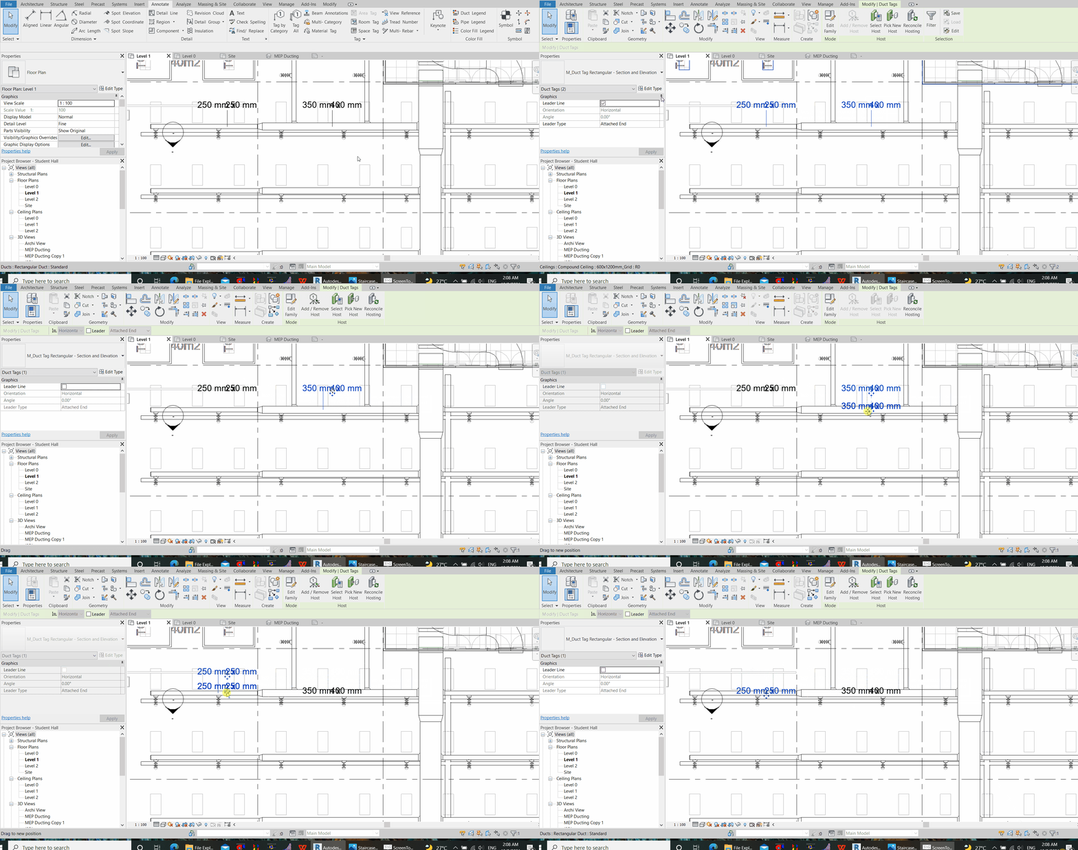
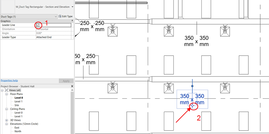
Click on the existing label, then on the properties pane, uncheck “Leader Line”. Then, click and hold on the grip icon and drag the duct label to the centre of the duct. When this is done, try to annotate another duct with the command “TG”. The changes should have been reflected in the new annotation.
(2) to change the label text colour to blue
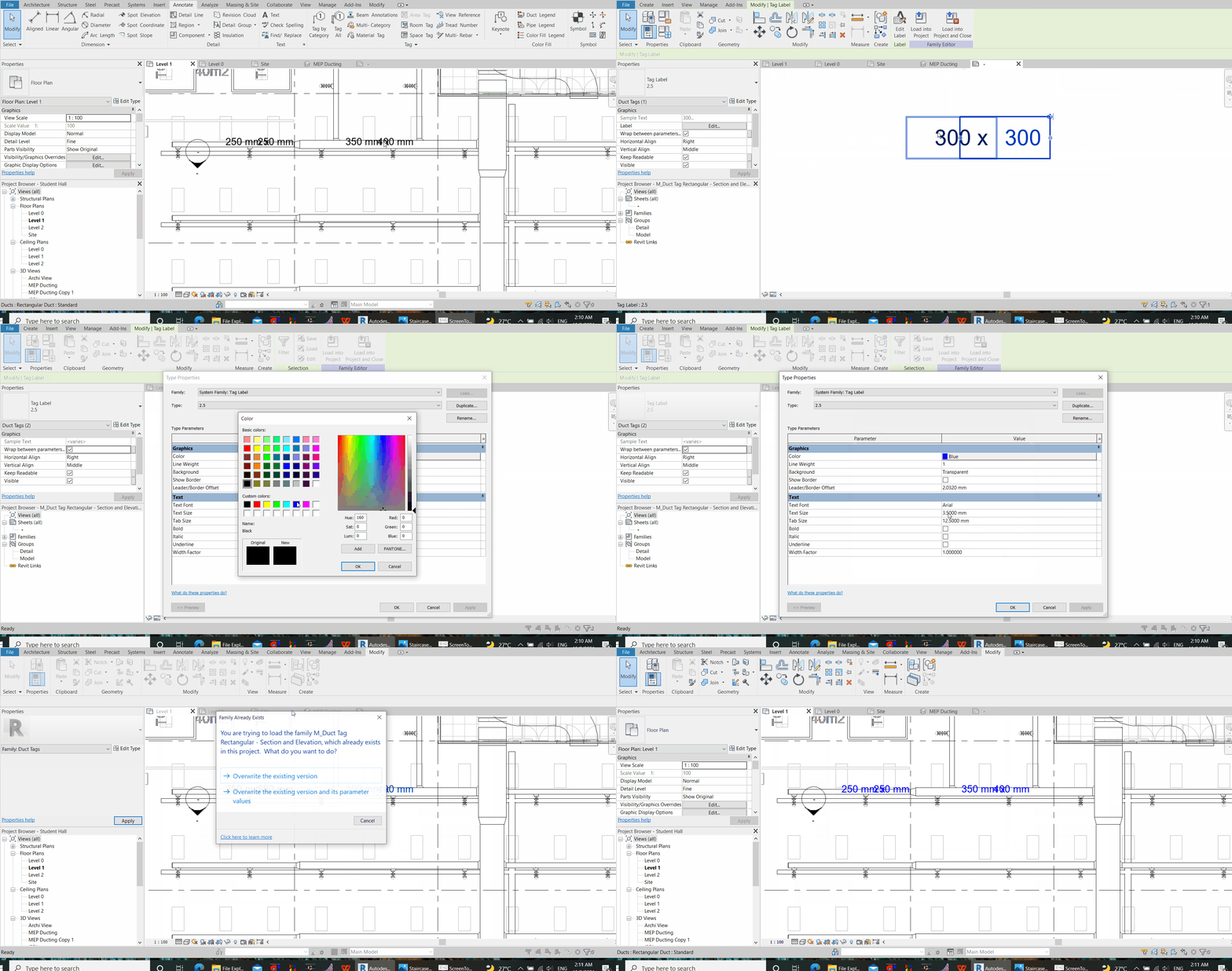
Click on the annotation, then “Edit Family” in the Modify Tab.
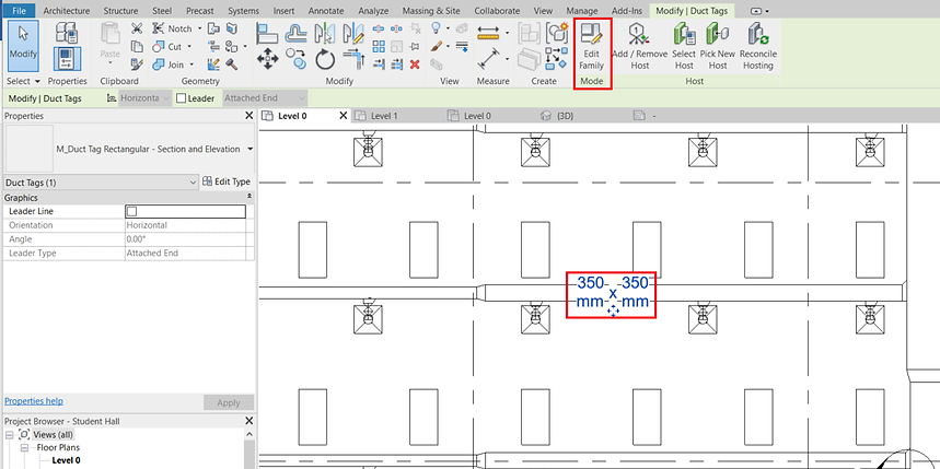
In the family editor, the family tag consists of 3 elements – 2 parameters (Duct Width and Duct Height) separated by “x”.
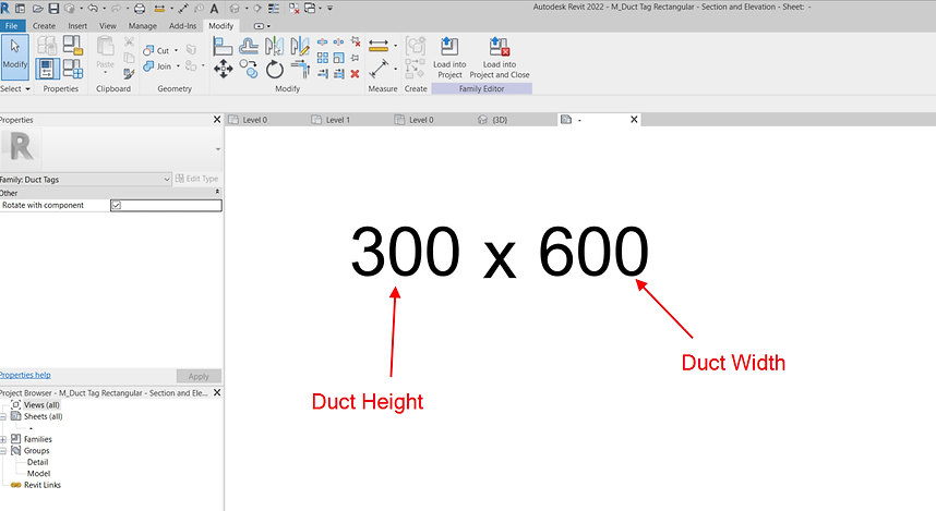
Select both parameters by clicking on one, and holding down the “Ctrl” key to select the next. Then, click “Edit Type” on the properties pane.
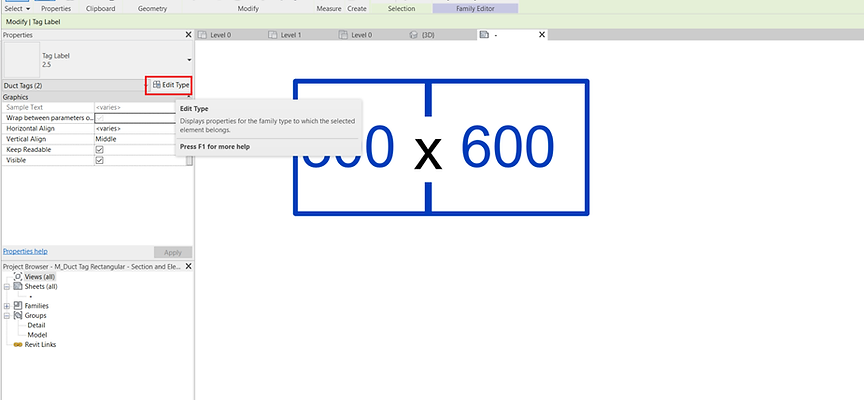
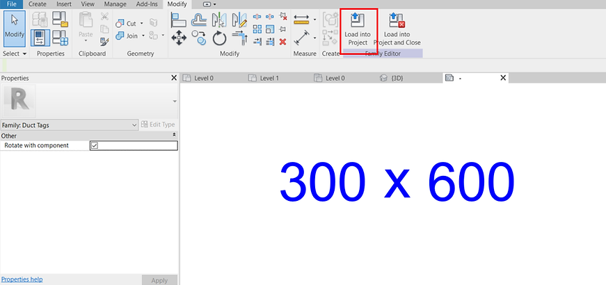
Change the text colour for both parameters to blue (or any colour desired). Other text styles such as text background opacity, text size, font, and width factor etc, may also be defined from here. Click “Apply” and then “OK” to exit the window. Then, click on the “x” and repeat the same steps to change the text style. Use the same method to make the texts background transparent.


Finally, click “Load into Project”, “Overwrite existing version and its parameters”, and observe the changes to take place.
(3) to remove the “mm” unit from the annotation, go to “Manage” and “Project Units” or use the Command “UN”
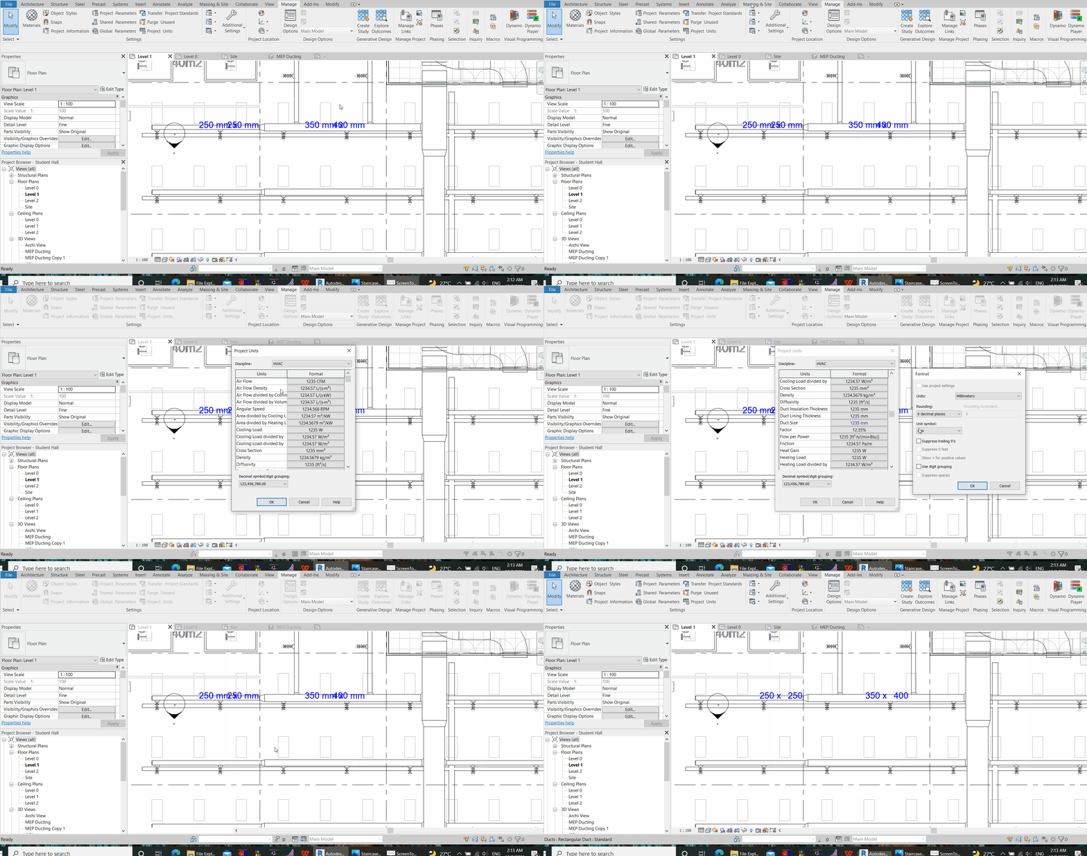
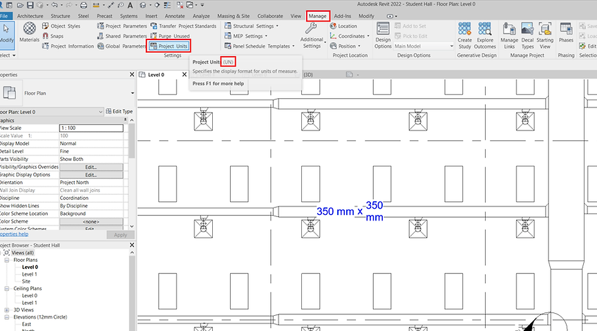
Select the relevant Discipline, in this case, “HVAC”
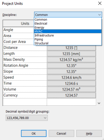
Then, scroll down to the relevant parameter, in this case, “Duct Size”

Change the unit symbol to “None”
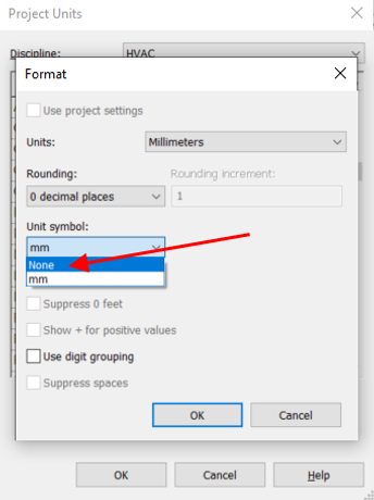
After pressing “OK”, the annotation shall become as follows.

(4) to interchange the parameters from “height x width” to “width x height”, setting of the parameters in the family file is required. Again, click on the annotation and then “Edit Family” in the Modify Tab. Refer to step (2). Click on the parameter and then “Edit Label”. This time, we want to define the left parameter as the duct width (and the right one as duct height).
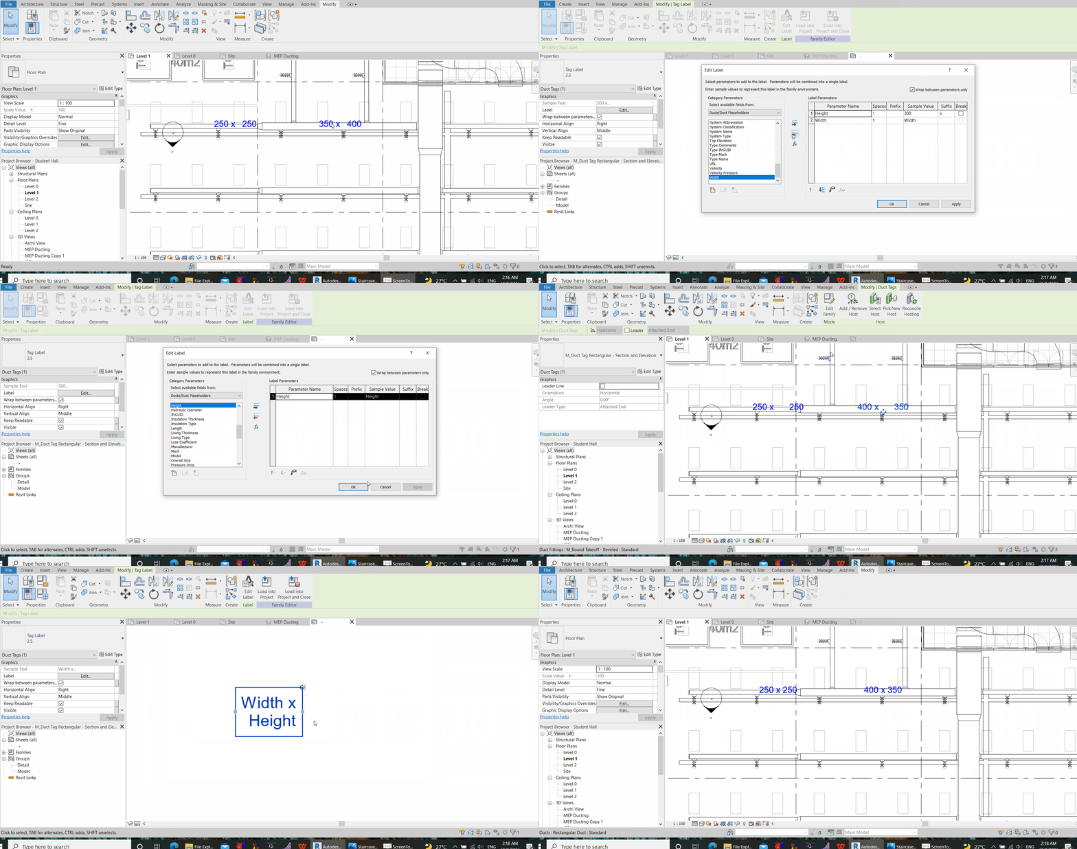

While editing the left parameter (left side of “x”), scroll down to look for the right category parameter, and click on the green arrow to add to the label parameter. These category parameters are those that have been defined in the ducting family.

Click the parameter “height” and then the red arrow to remove parameter from the list. Then, repeat the same actions for the parameter to the right side of the “x” but this time, remove “Width” and change the label parameter to “Height”
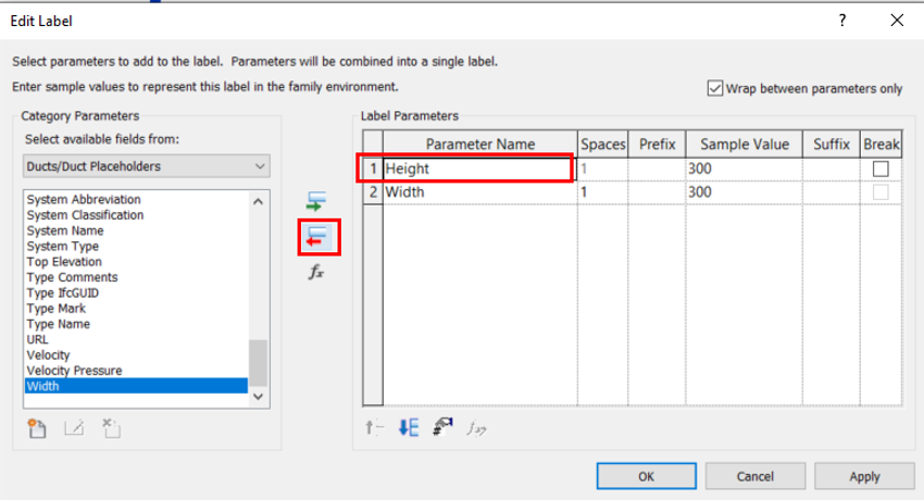
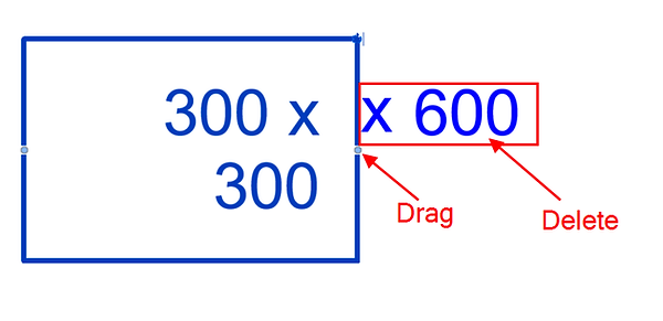
Alternatively, we can just use one label for both Width and Height parameters, by adding a suffix “ x ” after the Width Parameter.

In the Editor Space, drag the label box wider if both parameters cannot fit within one line in the same box. Delete parameters if they are no longer in use.
(Note: 300x300 shown in the box in the editor space is just a sample. In any other views, the annotation may become a 2-liner when the annotation length exceeds the box size. Always allow more lengths by extending the width of the box in the Family Editor Space).
Now that you have tagged one duct, you may now click “Tag All” to tag the rest of the ducts in your view. Then, scroll down to the updated parameter category and check the relevant category. This category can be defined in the Family Editor for the Annotation. When done, Click “Apply” and then “OK”.
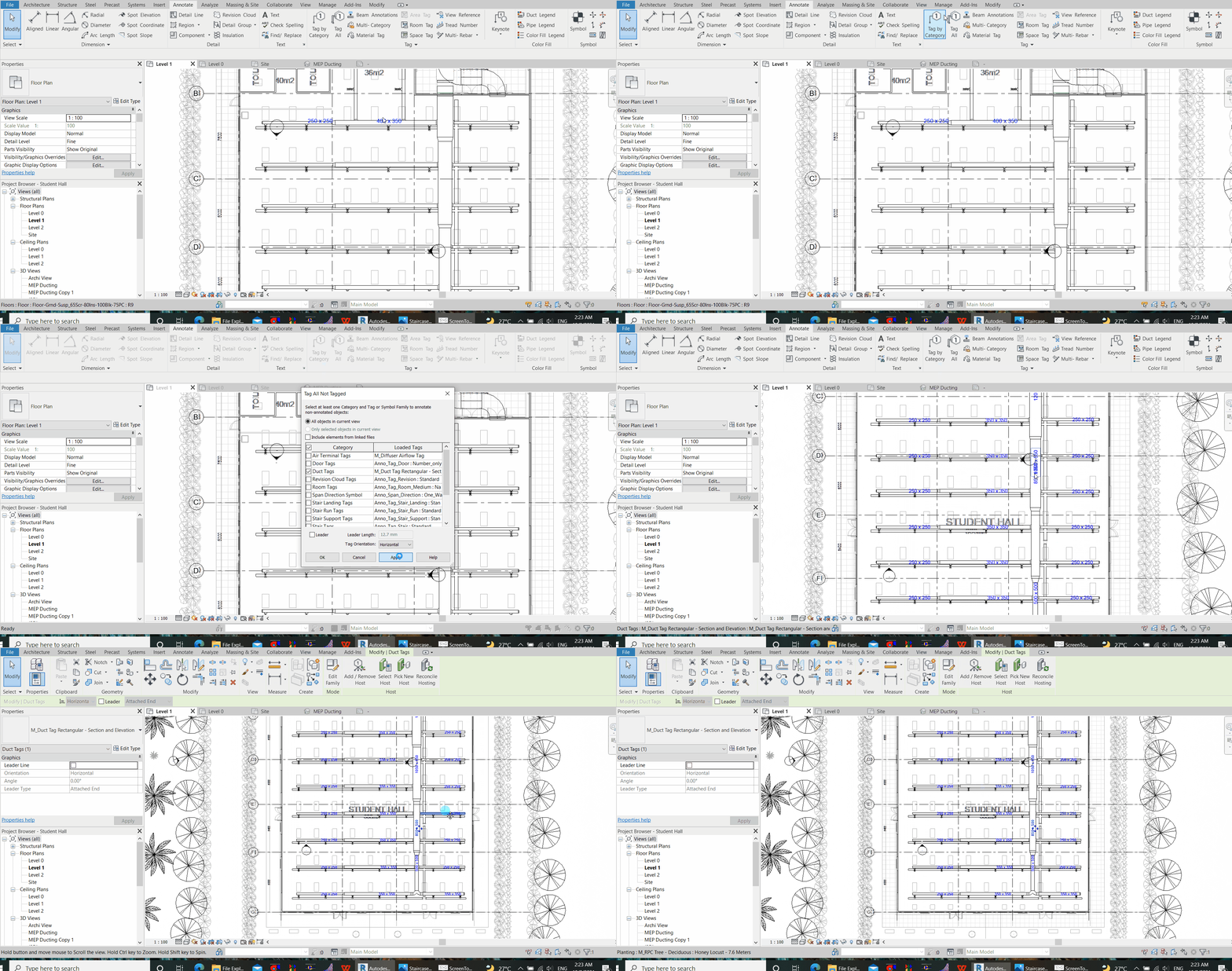
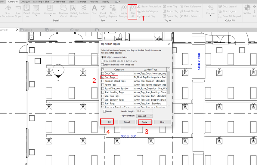
This shall enable all duct sizes to be labelled in the project.
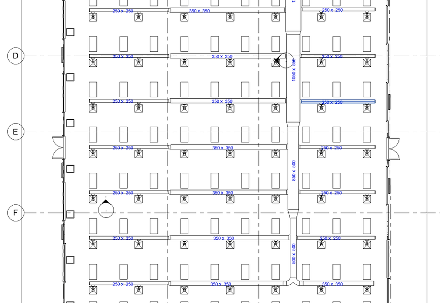
Exercise 2
Now, let’s annotate the airflow of all supply air diffusers by creating your own family (RFA File). Again, we first use the “TG” command to “Tag by Category”, then click on any of the supply air grilles. Similarly, a window will prompt you to load a tag for air terminals. Click “Yes”. If you managed to find a tag for diffuser, load one. Otherwise, Copy and paste any of the annotation family file and rename it to Diffuser Airflow (or any other preferred name)

To edit the family file, navigate to the file location in your file explorer and double-click to open the file.
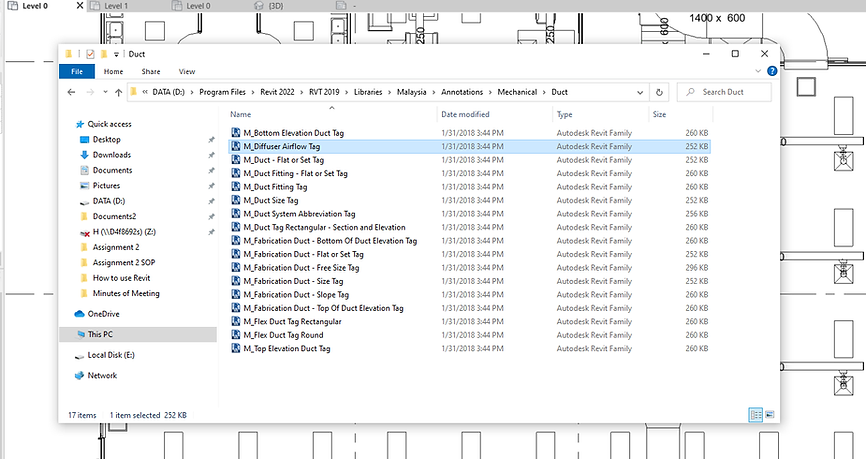
For my case, the annotation file was copied from a label annotation for “ducting”. Now, we would like to change the category to an annotation for “Air Terminal” instead. To do so, click “Family Categories and Parameters”, the one with a yellow Folder icon.

In alphabetical order, select the desired family category. In this case, we opt for “Air Terminal Tags”, and click “OK”. Note that this is the Category that we define for our selection for “Tag All Not Tagged”. (Add GIFs)
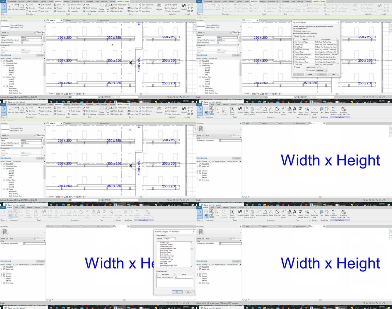
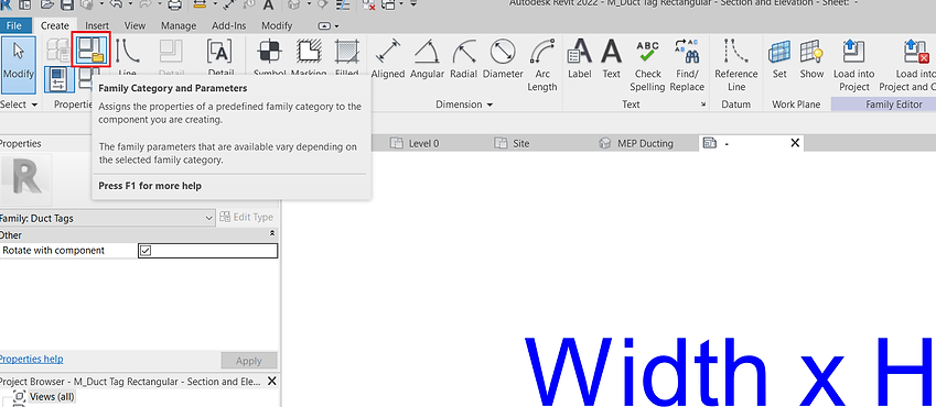

These then, whatever we should be doing will just be a repetition of the previous steps (in exercise 1) when we added the duct size annotation. For a recap, select on the annotation text on the editor space, then click on “Edit Label”

Then, add the parameter “Flow” to the Parameter List and remove the existing, unused Parameter (in this case, Size). Hit “Apply” and “OK”.

To edit Text Style, select the sample annotation text again, then click “Edit Type”. For instance, we change the background to Transparent. Hit “Apply” and “OK”, then “Load into Project”.

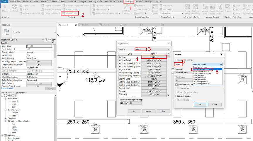
To change the airflow unit from L/s to CFM, go to the manage tab > Project Units (or use the command “UN”) > Select Discipline “HVAC” > Select Air Flow Format > and select the desired Unit (CFM). From here, you can also set the rounding to “0 Decimal Places”. Then, click “OK”.
Now that you have tagged one diffuser, you may now click “Tag All” to tag the rest of the diffusers. Then, scroll down to the updated parameter category and check the relevant. Click “Apply” and then “OK”.

Adding Annotation in 3D view / Locking or Creating a new 3D view
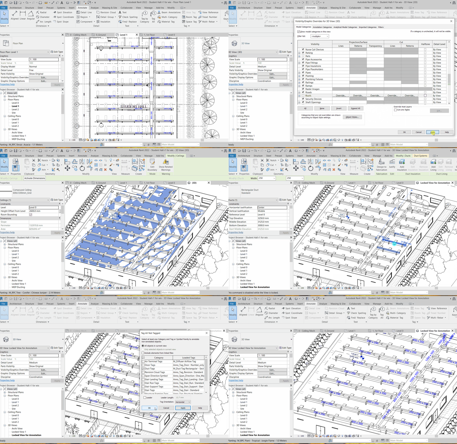
To add annotation in 3D view, we need to first lock the 3D view. In the 3D view, adjust to a desired perspective angle, then on the bottom left panel, click “Save Orientation and Lock View”, give the View a name (e.g. MEP Duct Label). Note: You may access to different views from the Project Browser Panel.
(Note: to not affect the original 3D view, you can right-click to duplicate a view from the Project Browser, rename and work on the Duplicated View)

Then, repeat the previous step for annotation.

The annotated 3D view looks like the following. You may still be allowed to zoom in and out despite the locked view, and you are allowed to delete or move overlapping labels.

To move a label, always look for the Grip icon. Bear in mind that moving a label in 3D view may take more require more time.

Annotation in 3D
To annotate dimension in three-dimension, we need to first lock the 3D view (Refer to the section “Adding Annotation in 3D view / Locking or Creating a new 3D view”). Then, use the command “DI” or click Dimension Aligned.

Select where you would like to measure from (for example, wall centrelines)
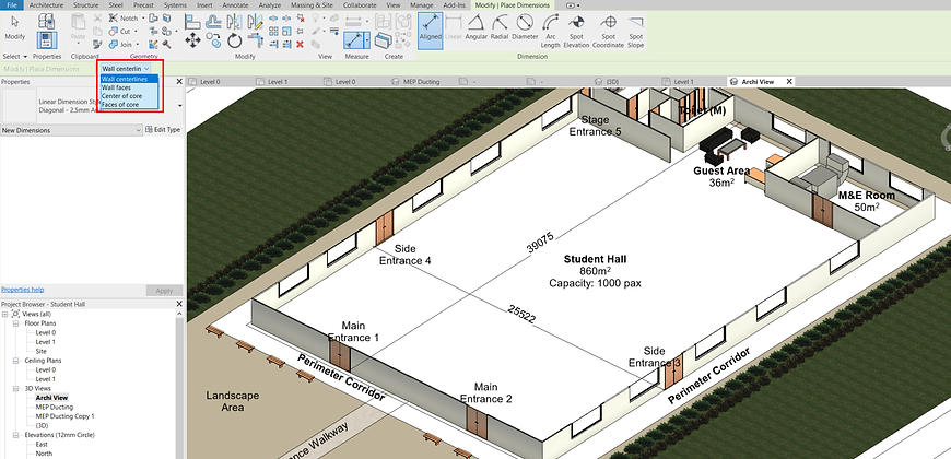
To start annotation, click on the “start-measure” point, “end-measure point” and then click on any empty spaces to register the measurement.

To edit annotation style, click on the annotation entered, and then click “Edit Type”. Else, use the match function “MA” to imitate other annotation style. If you find difficulties selecting your annotation, hitting your “Tab” key (repeatedly if needed) may help.

Assigning / Changing the Colour of a System
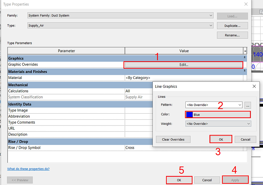
It is important to utilise colour for the differentiation of one system to another. For example, to differentiate a return air duct system (assigned magenta) from a supply air duct system (assigned blue).
To do so, right-click the “Supply Air” System, then click “Type Properties”. Then, change the colour for the system to your desired colour. Once applied, the duct outline colour will be updated accordingly.


Isolate
Sometimes, it is necessary to isolate a certain element or system for ease of visualisation or editing. As an example, let’s try to isolate the Air-Conditioning System.

Before that, we need to learn how to use “Tab” in combination with “Ctrl” to facilitate our selection (This is very helpful once you have mastered it)
Firstly, hover your cursor close to any part of the ducting network without clicking anything. Then, repeatedly hit the “Tab” key and observe changes in your selection preview. When the desired selection preview is shown, left-click to register the selection. Registered selection appears in solid blue.
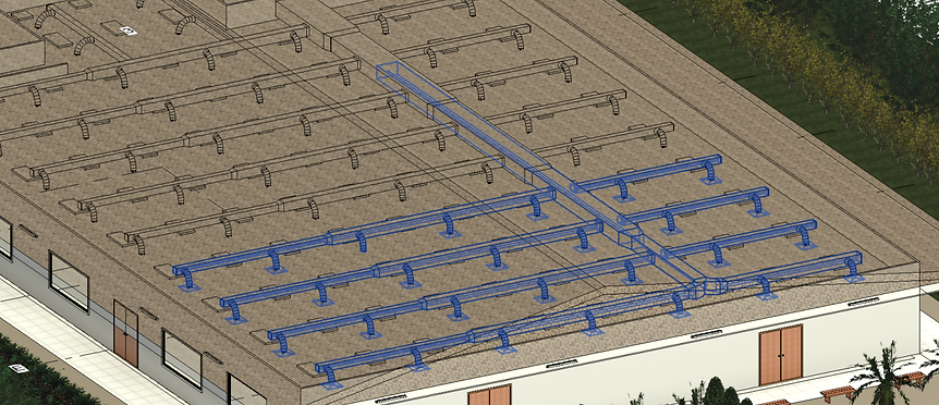
If none of the previews suggests the selection of the entire ducting network (or that of your preference), you may need the “Ctrl” key to help. Repeat the action by hovering your cursor to the next portion of the ducting network, then hitting the “Tab” key repeatedly until a desired selection is previewed.

Now, without bothering the “Tab” key anymore, hold down the “Ctrl” key to register the selection in addition to the previous selection (there shall be a small + symbol by the side of your cursor before your selection. Repeat until the entire system is selected (in solid blue shade)

Finally, use the command “HI” to isolate. To return to the original view, use the command “HR”
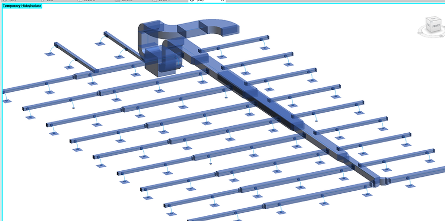
This method of selection can be very helpful in various applications. To quote one example, after you have completed drawing a Chilled Water Supply Piping Network, you want to duplicate a set for Chilled Water Return. What you can do is to use this method to select the entire network of Chilled Water Supply Piping (along with all accessories), and then copy and paste it by some offset. Then, go to the system browser (View > User Interface) to dissociate the copied selection from “Chilled Water Supply” and then assigned to “Chilled Water Return”. Of couse necessary adjustments may be needed but it definitely will help save a lot of time having to reconstruct the whole system over again. To “dissociate” and “reassign” a system to a selection, refer to the next section: Changing the System of Duct or Pipe Networks
Changing the System Type of Duct or Pipe Networks
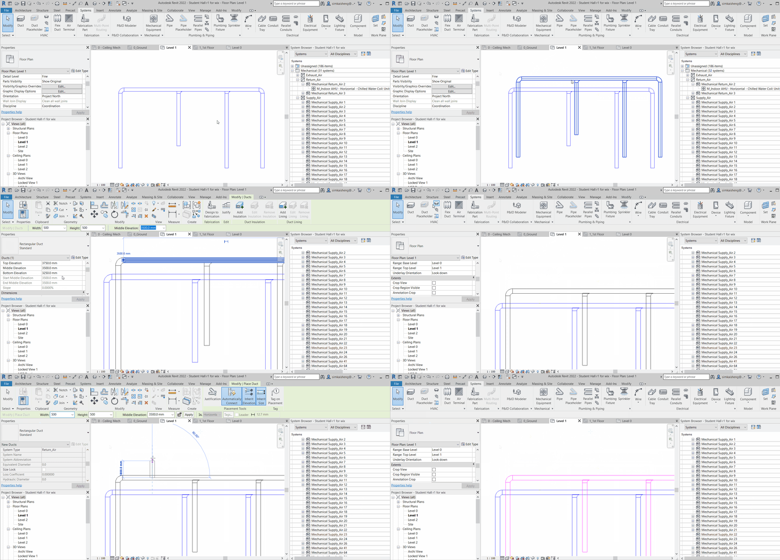
Changing the system of pipes or ducts can be very useful and at the same time, simple. As mentioned, one useful application include: After complete drawing a chilled water supply pipe network, we copy a set and change the system into chilled water return.
Below we show an example how we duplicate a network of supply air duct system, and change the duplicated set to a network of return air duct system.
Duplicate a supply air duct network
1. Firstly, hover your cursor over the duct network that you intend to duplicate
2. Hit the “Tab” key repeatedly, until the selection preview shows a selection of what you intend to include. Click to register the selection
3. Then, Copy and Paste your selection

Change the duplicated duct network from supply air duct system to return air duct system
1. Making sure that you have enabled “system browser” in your user interface, select your duplicated duct network as a system.
2. To select the system of a duct, hover your cursor over the duct network, and then hit the “Tab” key repeatedly until you see dotted lines. Click to register the selection
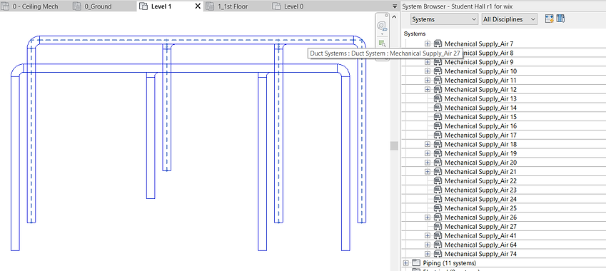
3. When a system is selected, the system will be shown highlighted in the system browser. Scroll down to see which system does it belong to. Then, right-click and “delete” the system.

4. Now, you will see that the duct’s system type becomes unassigned. (If you had assigned a colour to your system, unassigned objects turn back to its default black colour).
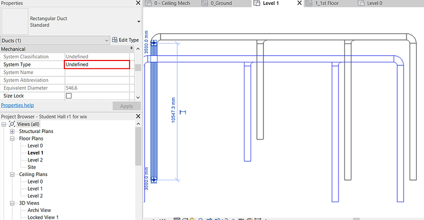
5. To assign a system to the duct network, simply draw a duct in the desired system and connect it to the system. Then, you may delete the duct afterward.

To add text
Use the command “TX”


To add leaders and text, click on the icons below
Texts properties (Font, Colour, Height, Background Opacity etc) can be defined by clicking “Edit Type” after selecting the text. Click “Duplicate” to create a “new text” with new defined properties.

To add texts onto 3D view, make sure the view is locked. (Refer to the section “Adding Annotation in 3D view / Locking or Creating a new 3D view”).
To relocate texts, always select the text look for the Grip icon . Sometimes it may be hard to select a text even when you hovered your cursor around it. In this case, hitting the “Tab” key may help.

Adding Sections
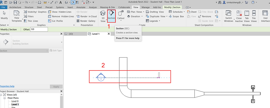
To add sections, go to the View Tab and click “Section”. Alternatively, use the command “KS” (Keyboard Shortcut), find Section and Assign “SEC” as a keyboard shortcut for section.

Cut the section across the desired view

Shift the marker around to adjust the section view, use the arrow to adjust the boundary (or depth) of view, and double click to navigate to the Section View.

Elevation
Elevation views shall exist by default for North, East, South and West Elevations. To access any of these elevations, go to the Project Browser.

Sometimes, the elevation does not show what we want to see. We can set this from the plan. Go to any plan, and look for the elevation marker. Click on the arrow tip and adjust the 2 lines to set the elevation view range. For adjustment, grip and drag the first line nearer to the marker, and use the arrow to set the view depth at the second line.

Drawing Staircase
As an example, we would like to add a staircase at the side here.

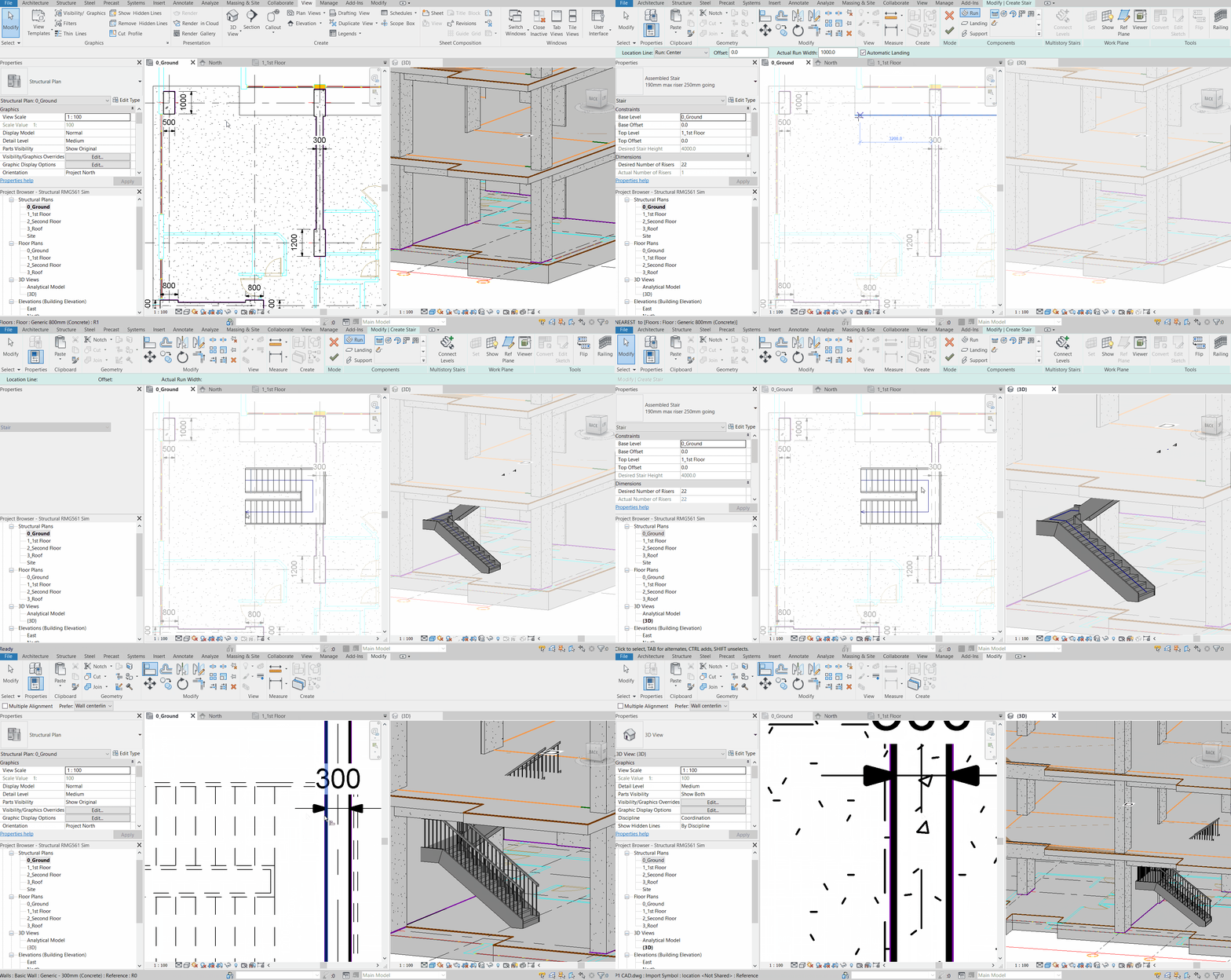
Before we do, we need to make sure that each level involved has “floor” (Slab) added.
Then, go to Architecture, and click “Stair”

Select the type of Staircase from the Modify Tab here, and then draw the stairs on the slab.


Draw the Staircase. If you need a turn, make the bend accordingly. At any point you are drawing the Stairs, you can know the number of risers that have been created, and those that have yet to.

The properties of the Stair can be adjusted from the Properties Pane by the side. The staircase width can be adjusted from the horizontal ribbon above.
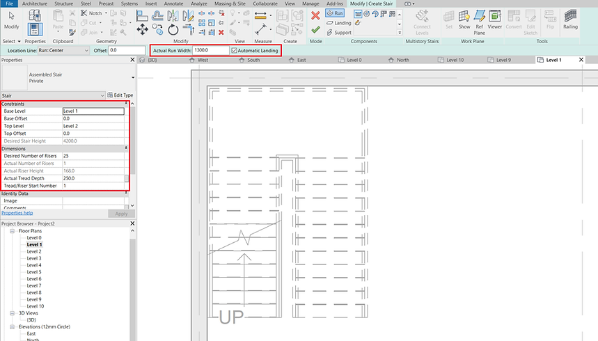
For better understanding, below shows the different parameters to set the staircase properties. The riser height is usually fixed. To determine the riser height, simply take the difference between the Base Level Height and the Top Level Height, divide by number of Risers. You can adjust the height by inputting accordingly, the number of risers desired.


Once you have completed with drawing the staircase connecting the 2 levels, you may adjust the staircase position, landing size etc. accordingly. Use the Align Command “AL” where applicable. Then, click on the green arrow to complete the staircase.

Now, we can draw a section to visualise the staircase drawn. Go to View, Section, and then draw a section across the staircase. Alternatively, go to the relevant elevation.

Double-click on the section head, or navigate to the section via the Project Browser to open the section. In the section, Select the Staircase, and then click “Select Levels”. This function enables rapid construction of staircase for the rest of the floors. However, this function is new and only available in Revit version 2018 and above.
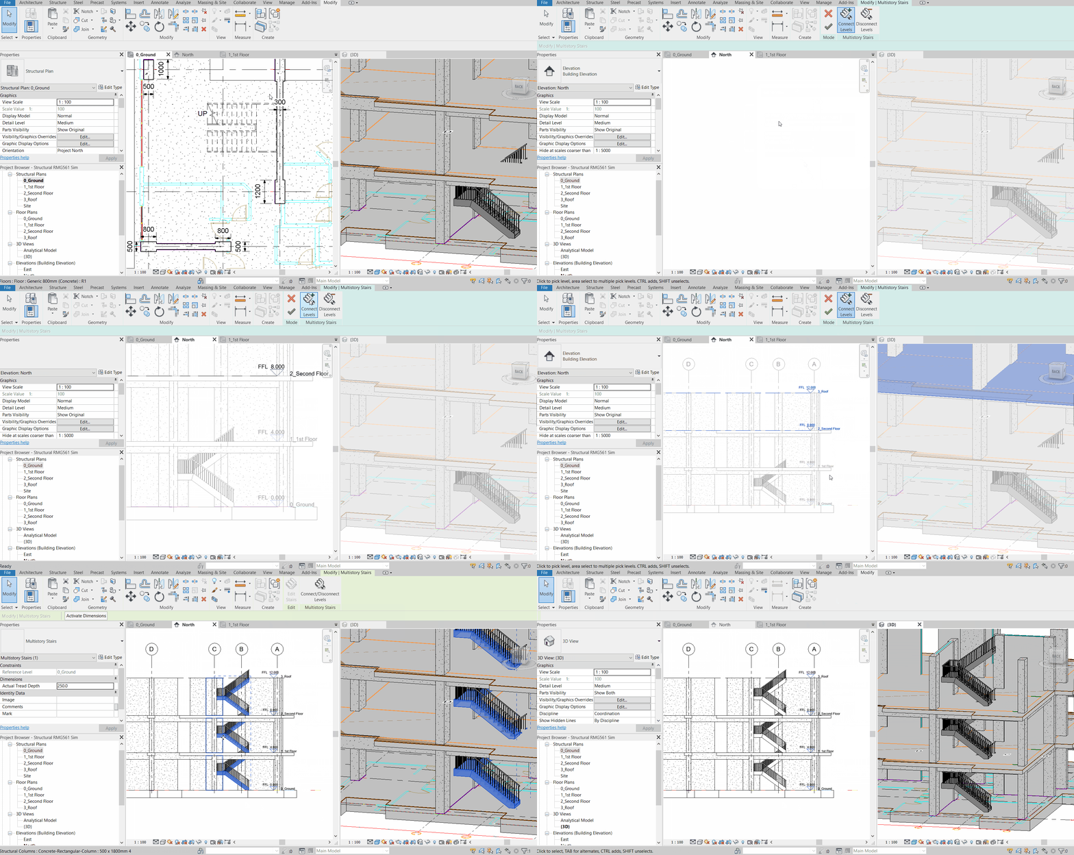

After that, select all the floors that we intend to populate the staircase to (Greyed out indicates the floors that have been completed), and then click on the green arrow to finish.

This will automatically complete the staircase connection to the rest of the levels.

Next, we need to cut the opening on the slab for the staircase. Select the slab (Click Tab Repeatedly if you are not able to select the Floor Precisely), and then “Edit Boundary”.
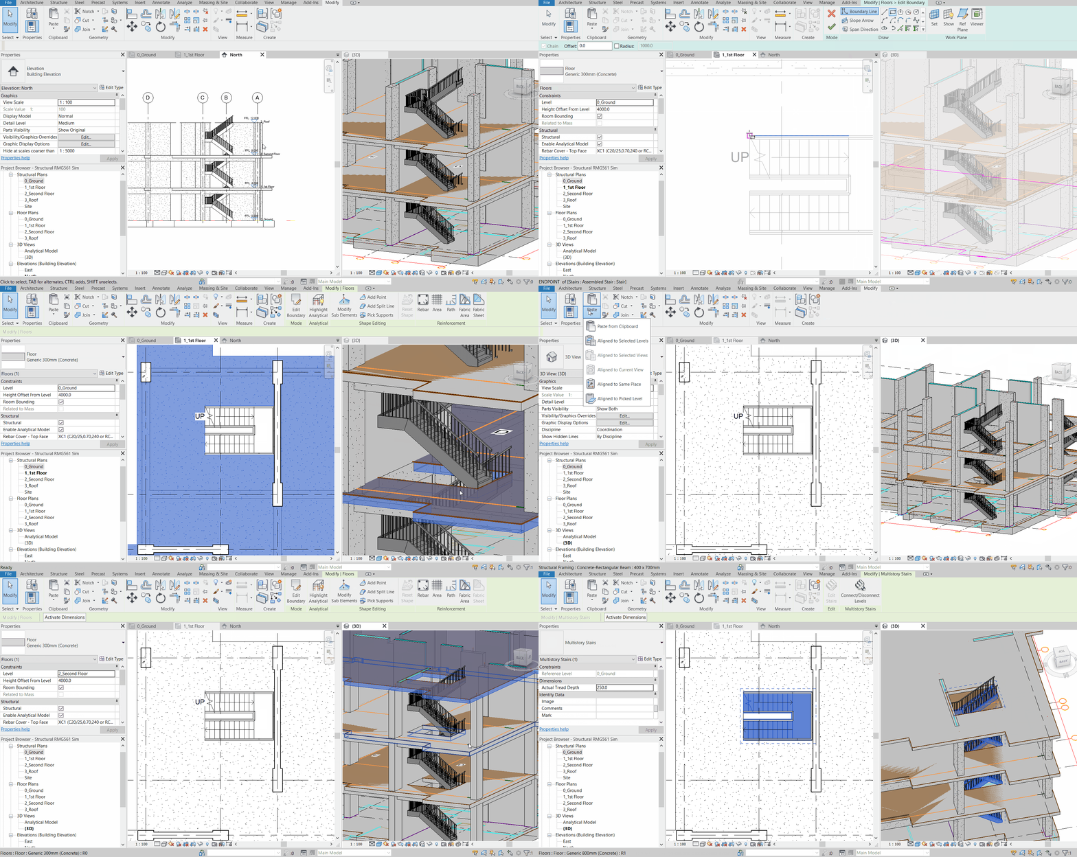

Defining the boundary of the floor by trimming off the old boundary line and adding new boundary line, and then click green.

The new floor slab shall become like this. Copy and populate the slab to the other levels from your elevation view.

Next, we can add a wall for the staircase enclosure, and a door for access.
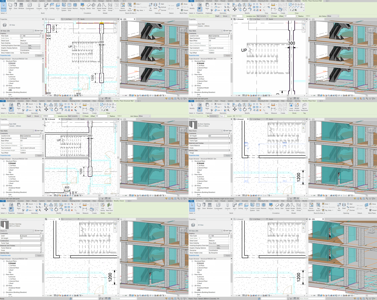


Copy and Paste Aligned to Selected Levels
Now, we want to propagate this (copy & paste the Walls and Door) to all other floors. To do so, select the element to Copy, then click the “Copy to Clipboard” icon. Alternatively, use the popular shortcut key “Ctrl + C”.

Then, go to any other level, and click on the drop-down for “Paste”, and select the option for “Aligned to Selected Levels”
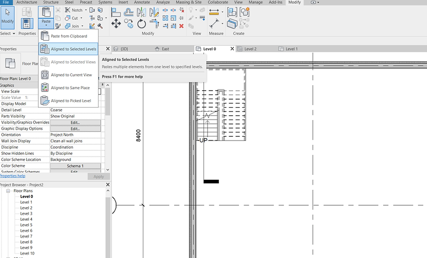
In the level selection, hold down the “Shift Key” or “Ctrl” key to select multiple Levels. Utilise the “Ctrl” key to deselect the levels of the source to copy (we don't want to paste to the origin). Then, hit “OK”

Room Label and Colour Fill
To identify a room, Click “Room” in the task bar or use the command “RM”.

Select the desired Tag style from the Properties Pane, then hover to the intended room and start Tagging.


Now, you can edit the tag name for each of the “rooms”

If you want to manually define the room boundary, use the “Room Separator” function, where you can “draw a line” to mark the boundary if there is no architectural wall to tell the boundaries apart (for example, when the room boundary is a linked structural model). All you need to do is to draw along the linked components (shown red below) or those which Revit’s “RM” function does not consider as a boundary for your room.

To copy room tag to the other floors rapidly, use the method below.
First, select everything in the origin Plan to copy.
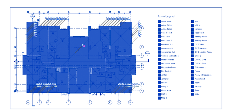
Then click filter and check only those items you are interested to copy, then click “Apply” and “OK”.

Click “Ctrl + C” to Copy everything selected to Clipboard, then, click the drop-down from “Paste” and “Aligned to Selected Views”.

Check the floor you would like the details to be copied to, and then click “OK”

Now that the Room Label is done. We want to colour each of the Room with legends of distinctive colours. First, go to Analyse Tab > Colour Full Legend

Place the legend at any empty space by the side
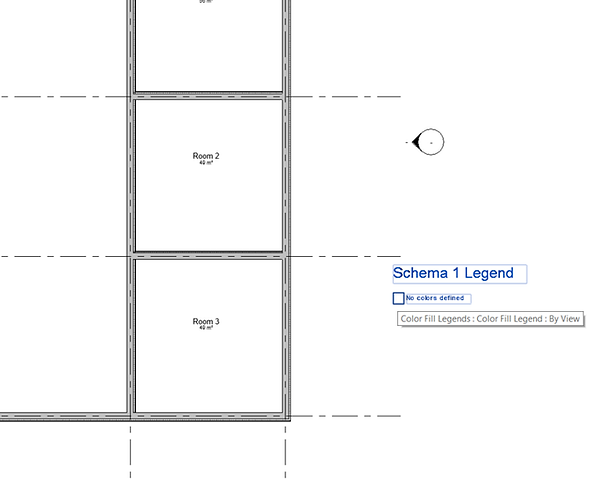
Then, select the legend and then click “Edit Scheme”
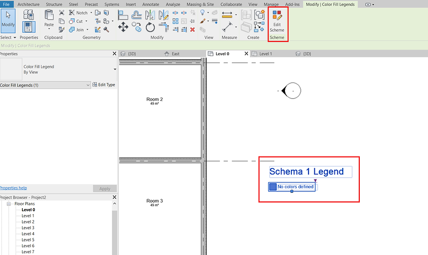
For our case, select “Rooms” as the scheme category, and then rename the Legend Title to “Room Legend”.

For our case, select “Rooms” as the scheme category, and then rename the Legend Title to “Room Legend”.
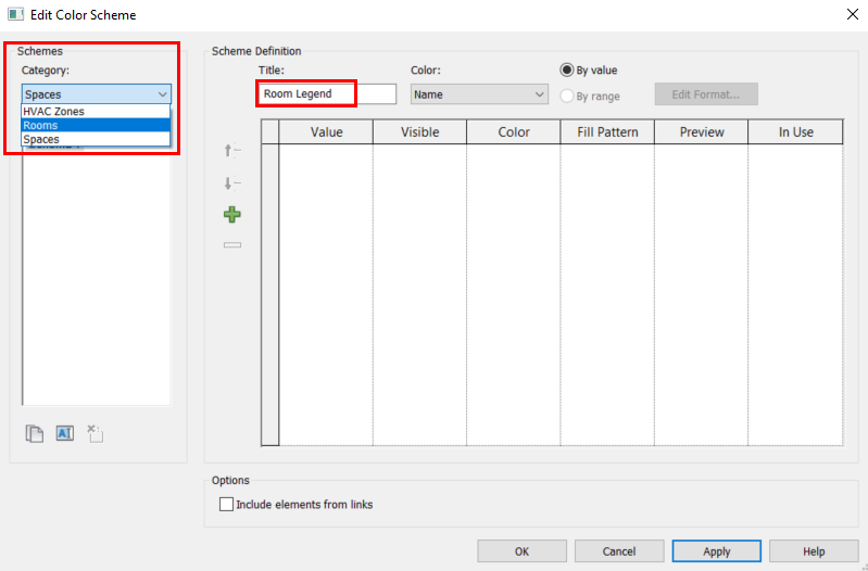
Then, select, “By Room Name” as a method of “Defining the legend for the Rooms”. The legend title can still be edited per the last step.

Upon clicking “Apply” and “OK”, the Colour Fill Legend will be formed like the following example.

Printing Sheet / Titleblock
Printing in Titleblock has become much easier in Revit than in AutoCAD, considering any Views can be “extracted” from a single model into any “Sheet” of paper, and the enhancement of setting the drawing scale in Revit. To transfer “View” into “Sheets”, we are first to add New “Sheets” as shown below.

Then, select the sheet size and template. If there is none, load from a library. (Note: Titleblock and Sheets are also a Rvt family file). Once loaded, we may edit all the information in the Titleblock.
Zipped File for Revit Titleblock RFA

Now, to add a “View” into this “Sheet”, just select any view from the Project Browser, drag and drop into the “Sheet”. By selecting the Viewport, the view scale can be adjusted directly from the properties pane, and got updated real-time in the “Sheet” (You will only need to ensure the view can fit into your paper). You may select “custom” to enter a custom scale.
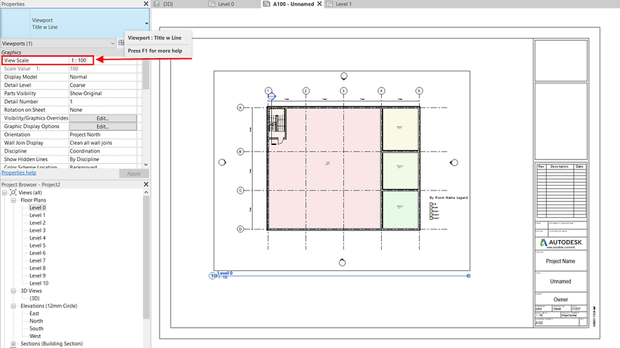
To adjust the boundary of the View, navigate to the View itself via the Project Browser. Then, click “show crop region” on the bottom left panel.
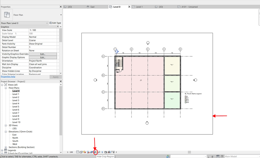
Once visible, you may adjust the view boundary accordingly. Hide the crop region again when done adjusting if you do not wish to see the boundary in your “Sheet”

.jpg)
.jpg)